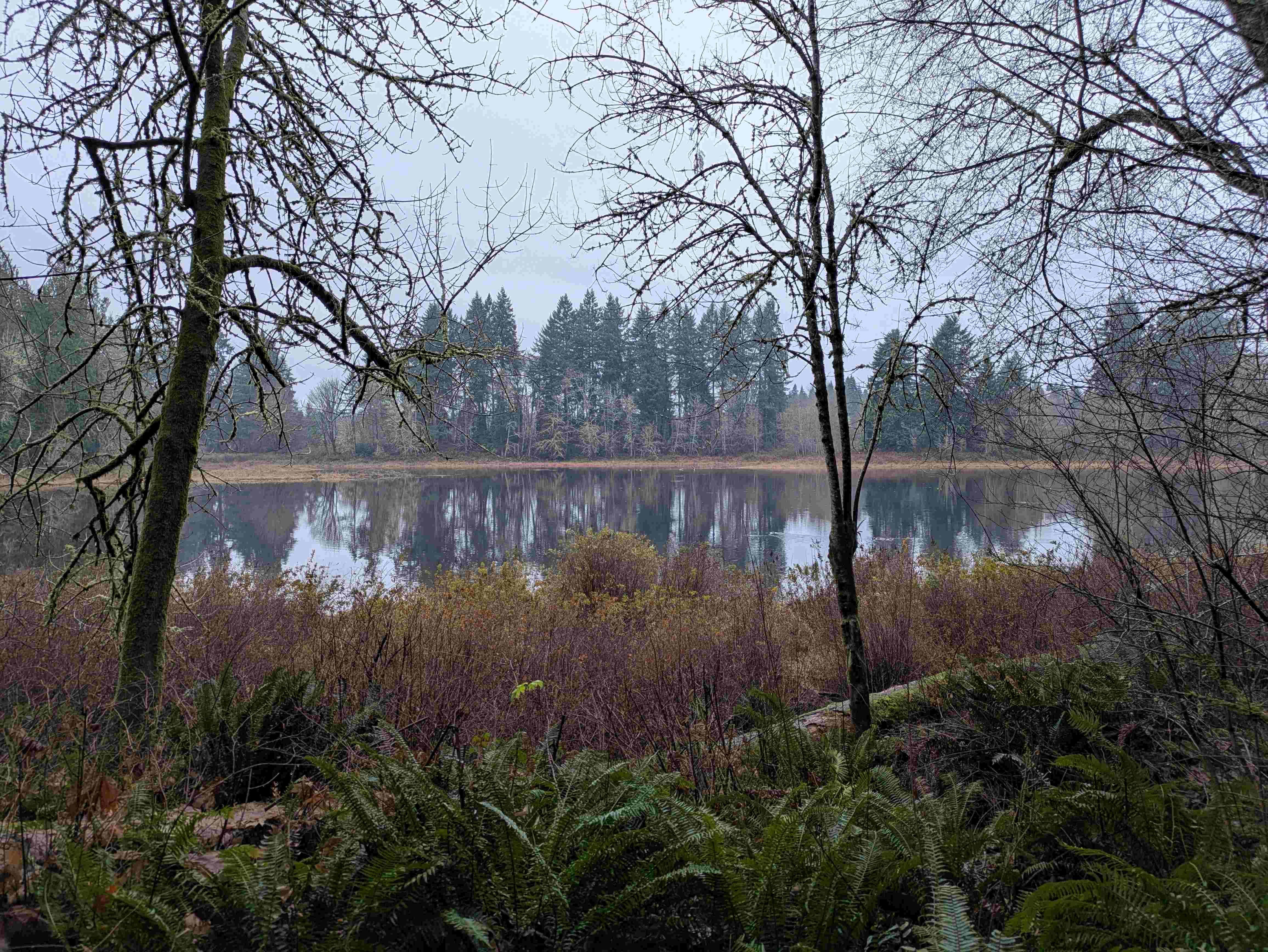
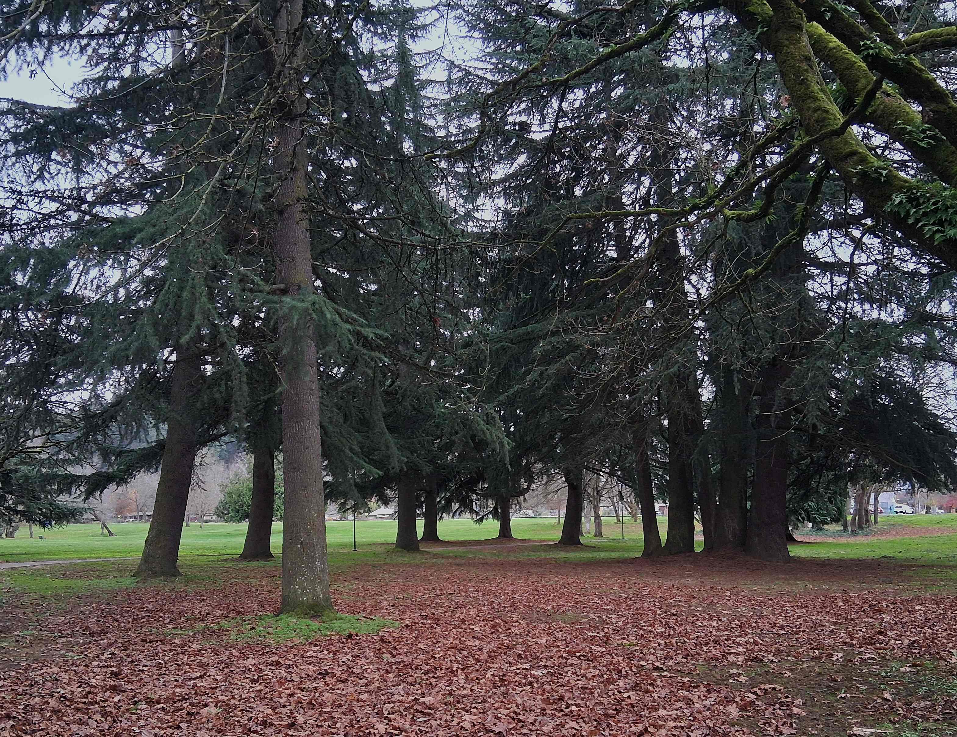
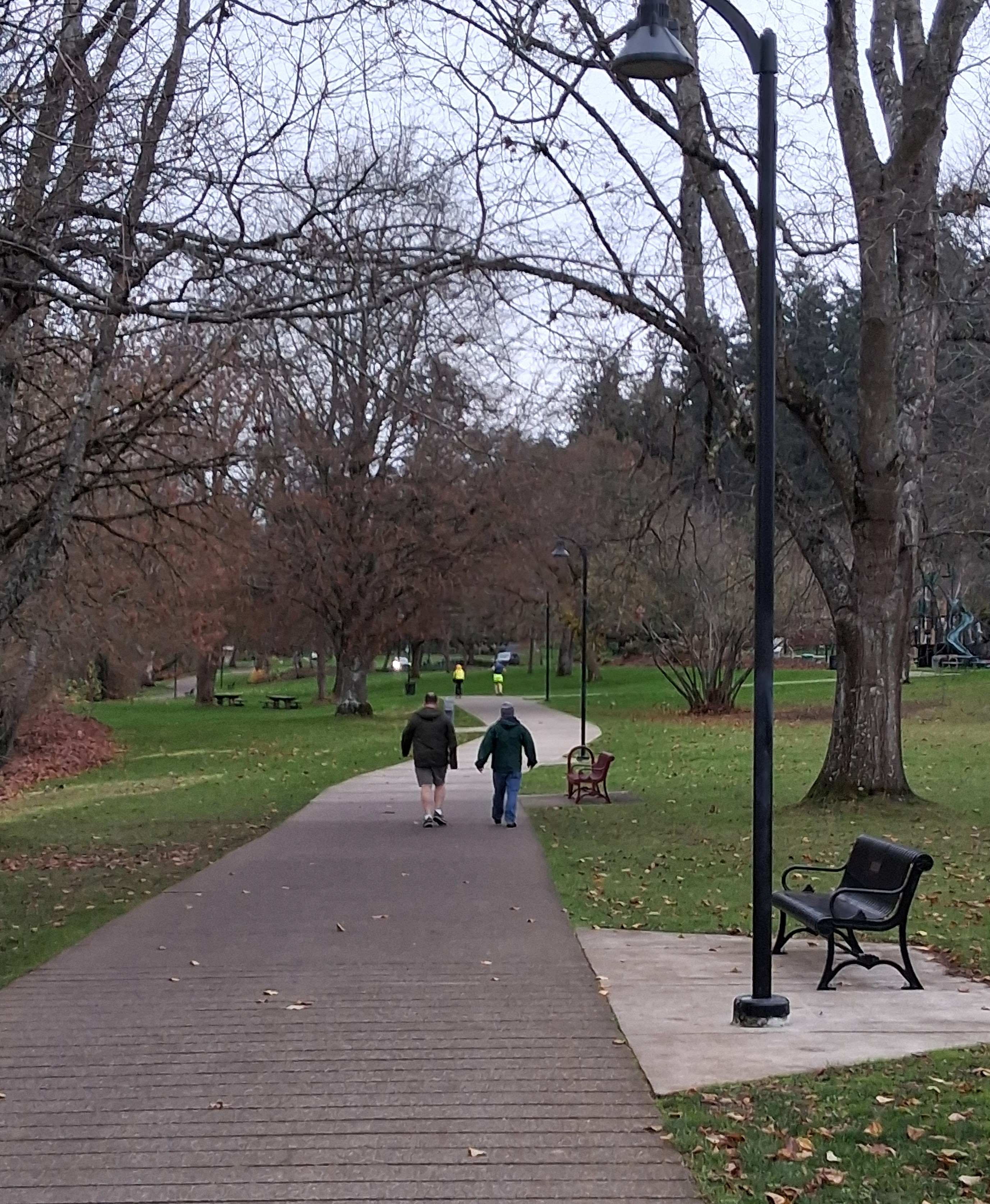
Need to relax and reflect? You could walk the Chehalis Western Trail outside Olympia, WA, where this photo was taken by my daughter, Yukyo, on New Years Day, 2026. The trail is the longest shared-use path for cyclists and hikers in the region. It occupies an abandoned railroad corridor that was once used by the historic Weyerhaeuser-owned Chehalis Western Railroad. [Photo Emily/Yukyo Vollmer, Click on image to enlarge]
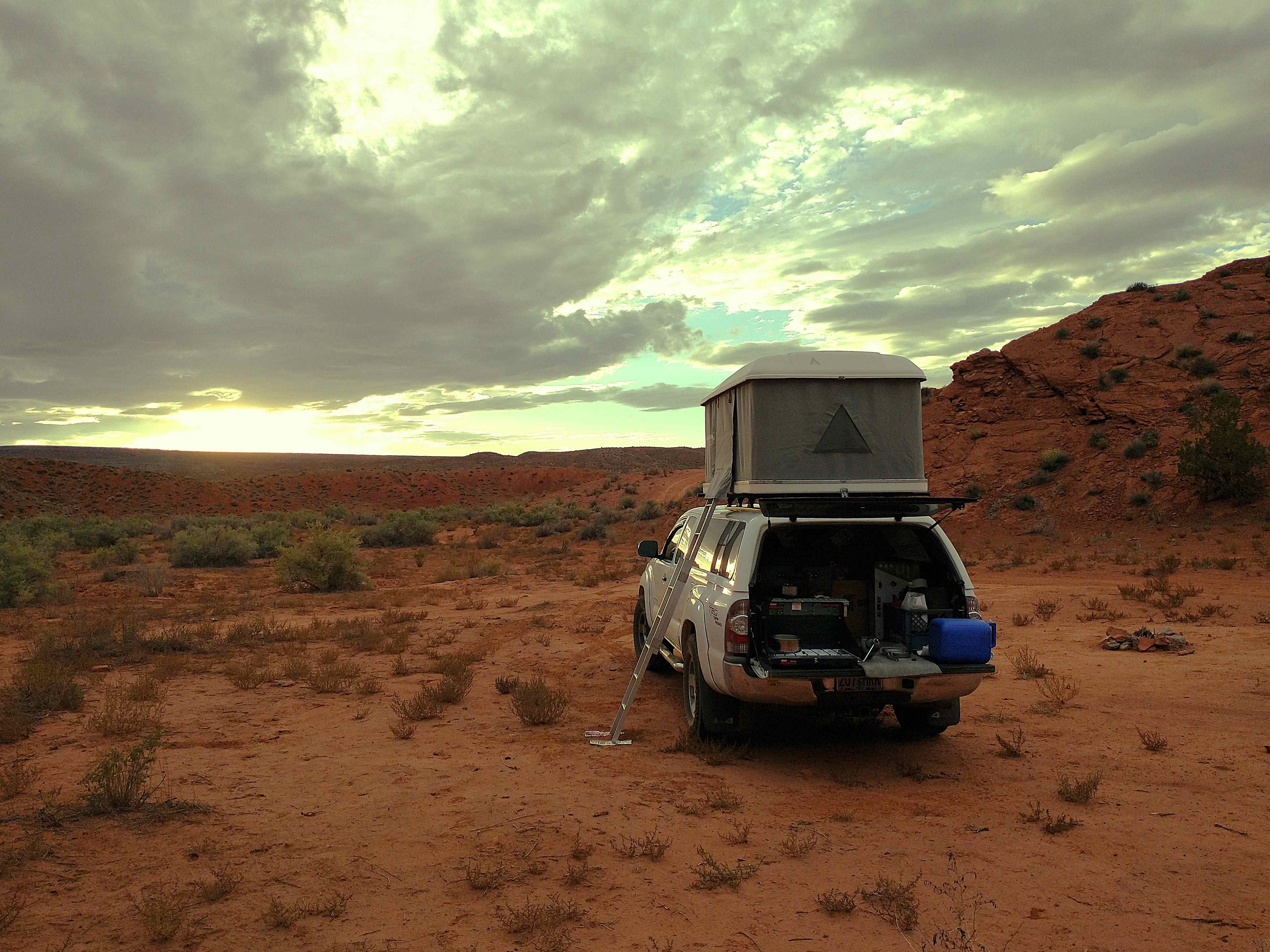
Where to go? Toward an expansive horizon is always my first choice. In the case of Chaco Canyon Road, the southern exit from Chaco Culture National Historic Park, it was 40+ miles of dirt road across the Navajo Reservation with the warning sign declaring, “Road not maintained, may be impassable to passenger cars.” There are no structures, no signs of habitation the length of that road. There are steep drops into and out of arroyos that flood with cloudbursts, as well as deeply rutted mud slumps that require 4WD to cross even in dry weather. There are no guarantees. But being alone with the unknown is a great way to get to know yourself. [Photo Max Vollmer, Click on image to enlarge]
Meredith Jane Monk (born November 20, 1942) was an American avant-garde composer, performer, director, vocalist, filmmaker, and choreographer. She was awarded the National Medal of Arts by Barack Obama.
I am celebrating women with the strength to follow their conscience, their passions, their dreams despite the risks associated with doing so. Without them the world would not be as rich and beautiful as it is.
Celestial Transients. Artistic rendering by Olena Shmahalo for Scientific American magazine.
Happy Solstice! As good a day as any to talk about ” . . . Celestial transients, which are astronomical objects that appear suddenly from nowhere and usually disappear soon after, that contradict the standard truth that the universe changes predictably and slowly over billions of years. They include what the typically staid National Academy of Sciences called “the most catastrophic events in spacetime.” [Quote from a Scientific American newsletter article titled, Mysterious Bright Flashes in the Night Sky, December 16, 2025, by Ann Finkbeiner and Clara Moskowitz. [Click on image to enlarge].
This is a relatively long read, but well worth the time it takes if you are feeling self-important at the moment. Prepare to be humbled by the immensity and the mysteries of the cosmos. Astrophysics is experiencing a golden age, thanks to the tools . . . orbiting telescopes, ground based radio telescopes, stellar and interstellar probes, etc., and the ever greater computing power available to process data. Of still greater importance is the international cooperation of scientists made possible by the World Wide Web.
Go to www.scientificamerican.com to sign up for the free Today in Science newsletter. You can then choose from specific newsletter topics like: Mind & Brain, Health & Medicine, etc.
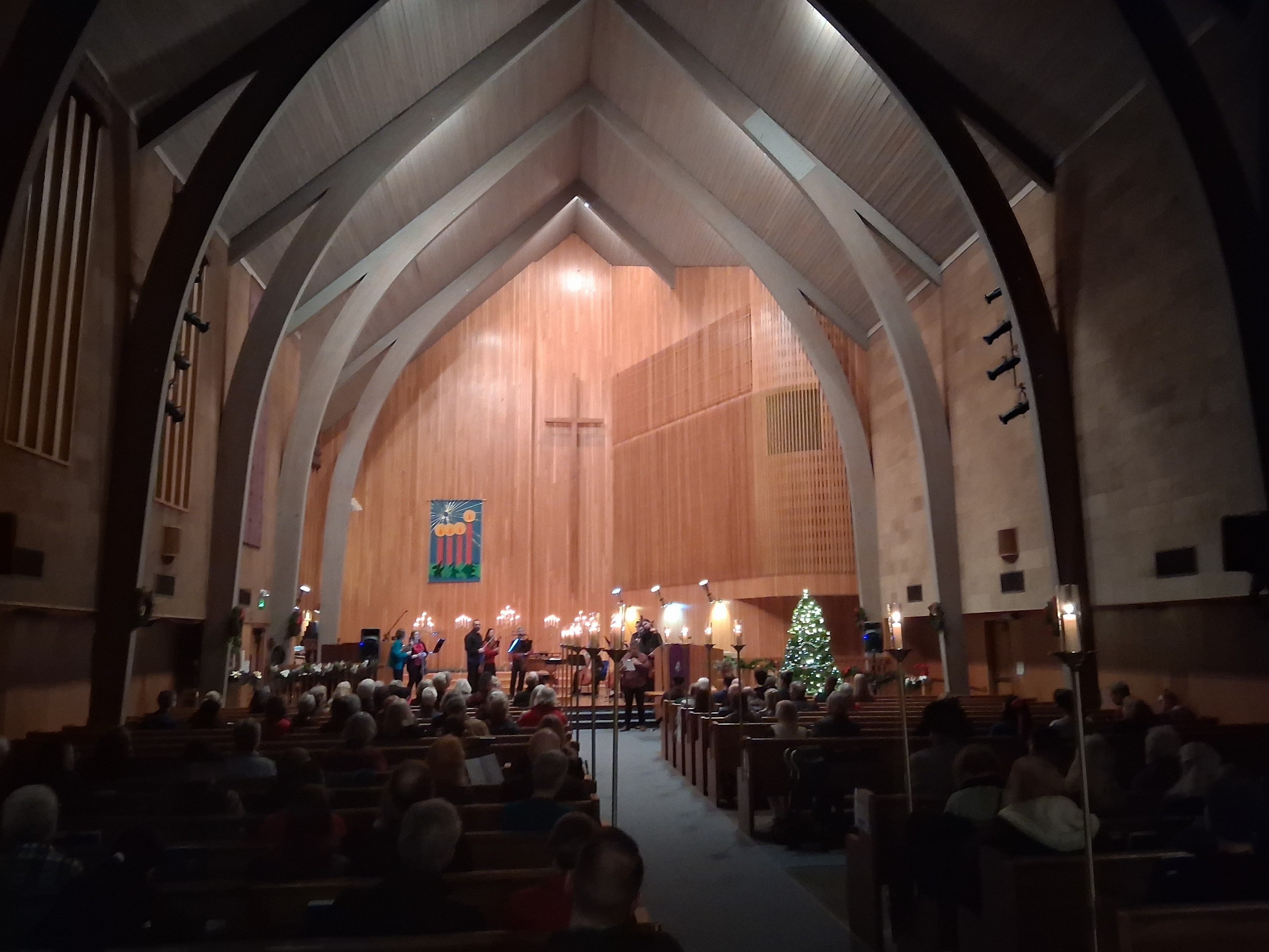
Oregon Mozart Players Candlelight Concert 2025 at Central Presbyterian Church, Eugene, OR
I’ve volunteered for the Oregon Mozart Players off and on for over 25 years and was happy to usher once again for this year’s Candlelight Concert. Beautiful music for the season. The program included Alessandro Scarlatti’s Christmas Cantata, as well as a Concerto Grosso by Archangelo Corelli, and Suite III from Ottorino Respighi’s Ancient Airs and Dances. Even the names are musical. My favorite was a 20th century Christmas Suite by English composer, Alec Rowley, based on traditional English carols. [Photo Max Vollmer, Click on image to enlarge]
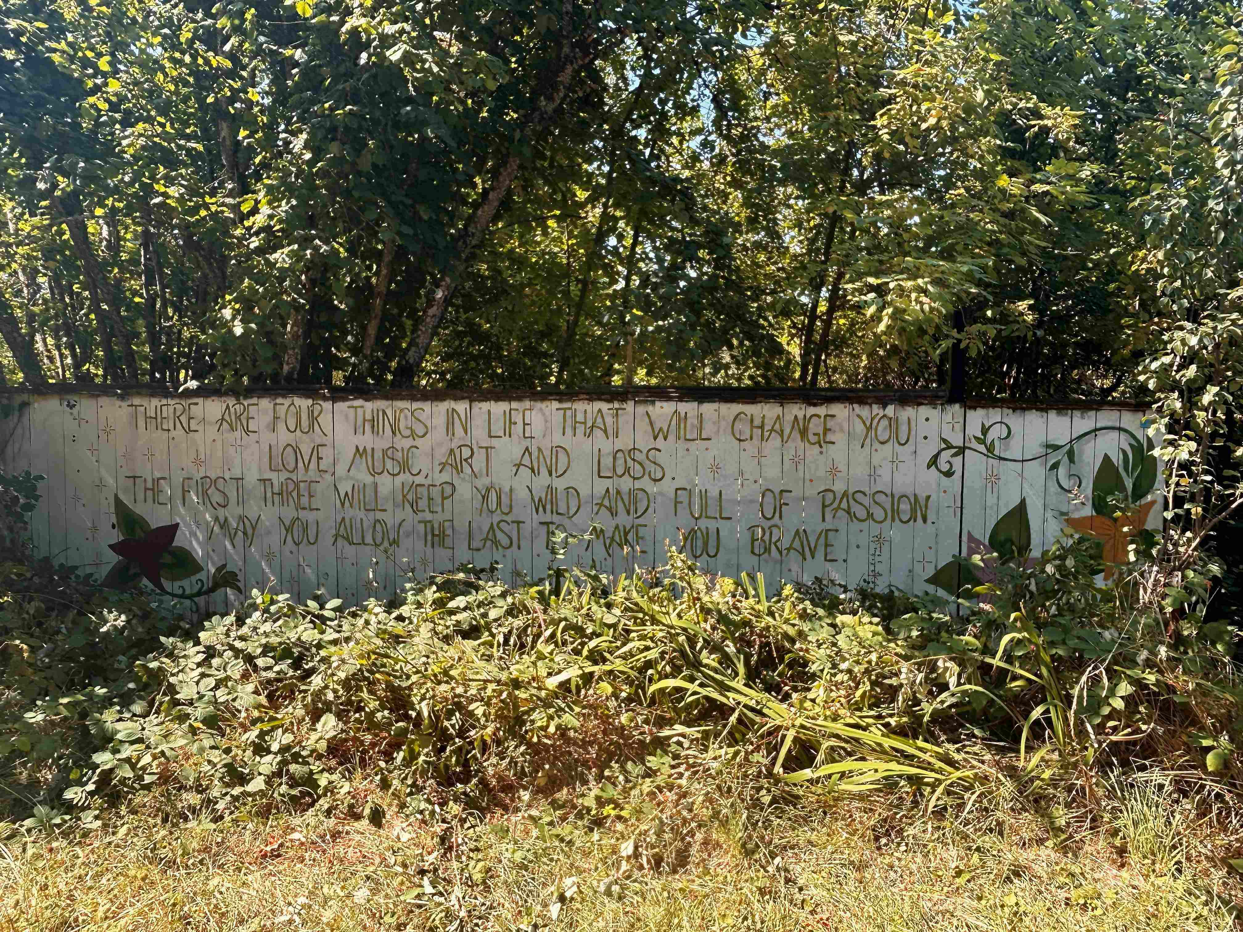
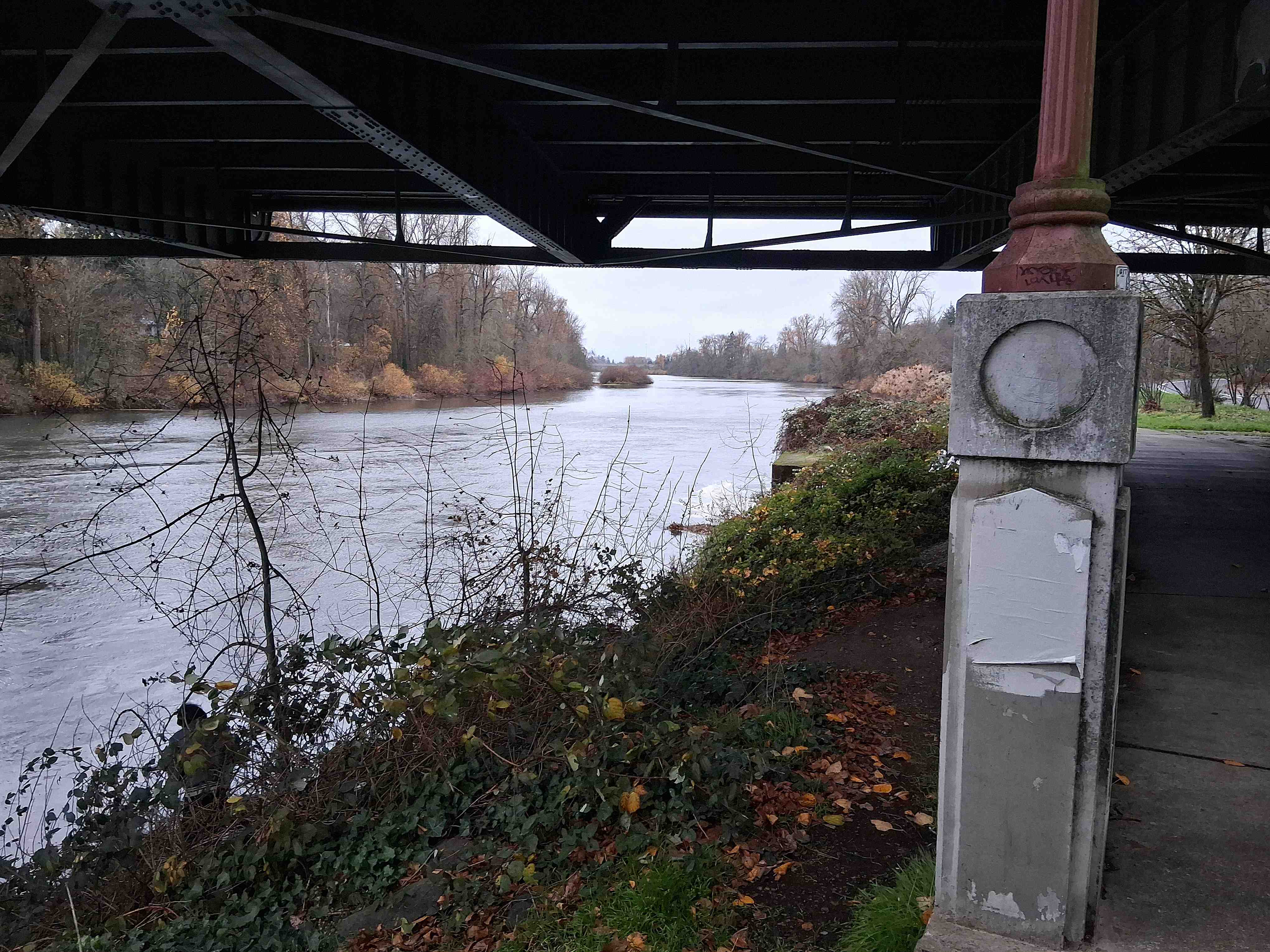
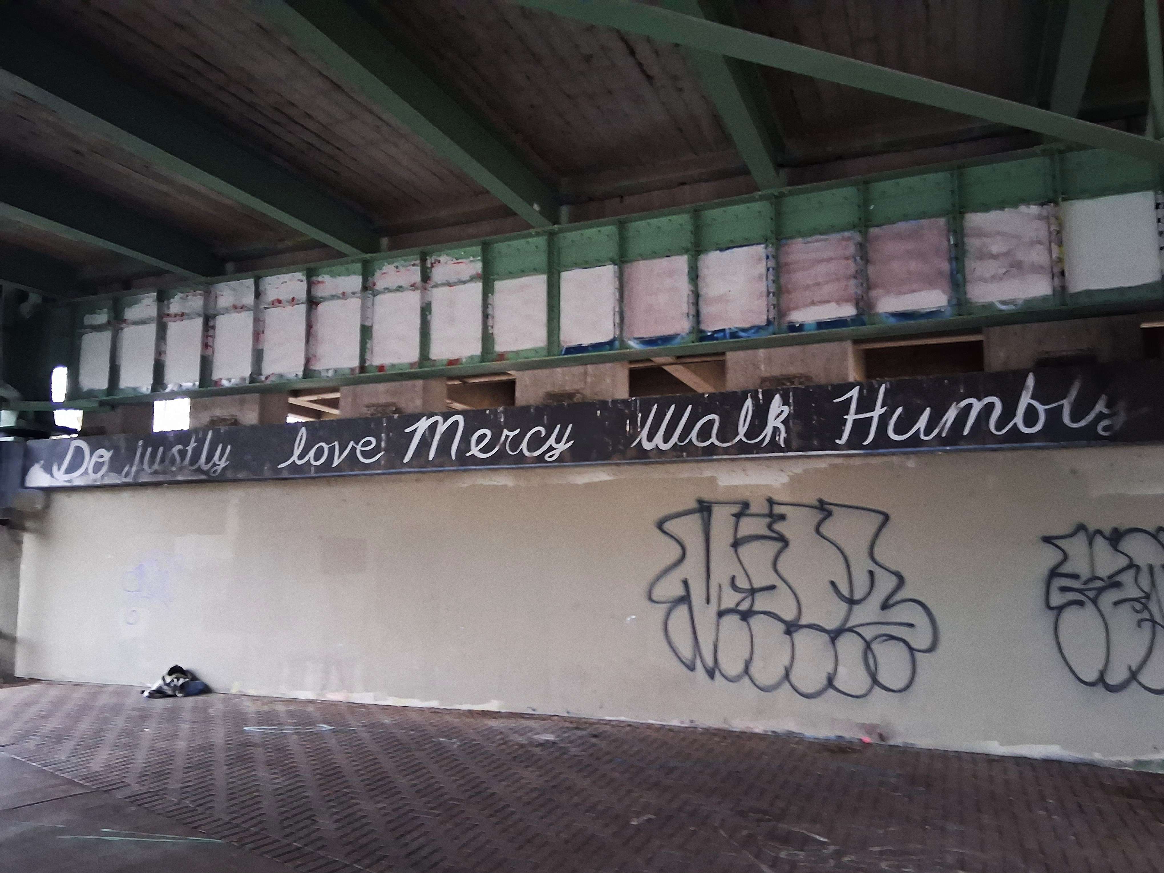
I took the photo on August 28 when Kat and I took our walk along the West Bank. Today I walked the Willamette River Trail from Skinner Butte to this spot and beyond in 60 degree weather and full sun. The message is as clear as ever. In loving memory of Kathleen “Kat” Jenison, October 8, 1955 – December 10, 2025. [Photo Max Vollmer, Click on image to enlarge]
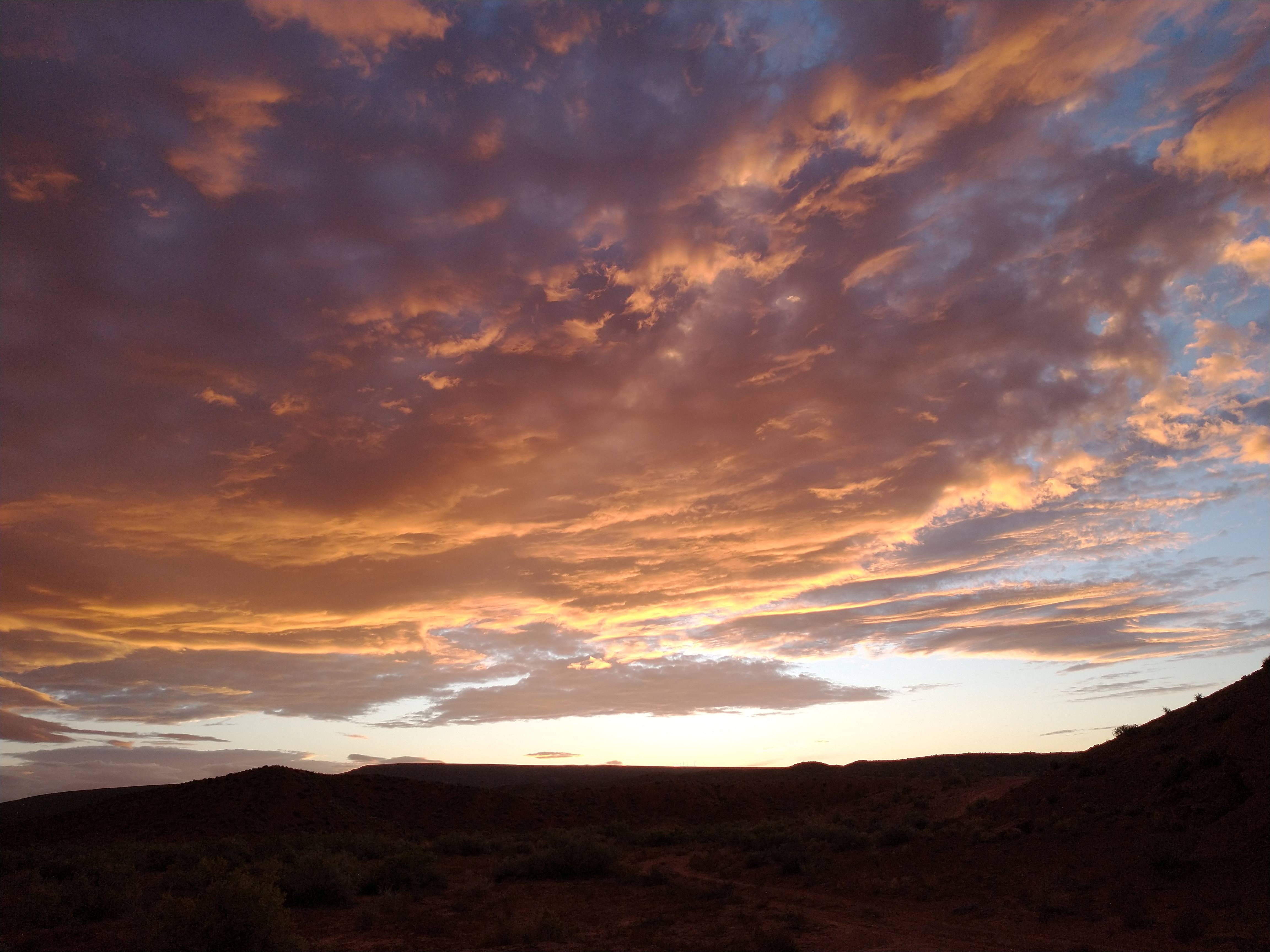
The open road and the Southwest, especially Utah, are never out of my thoughts. Spring and Fall are the best times to visit the desert. [Photos Max Vollmer, Click on any image to enlarge]
EveningChanging colors over Comb Ridge, looking southFading light to the west.
Young adventurer and lover of wild places , Everette Ruess, disappeared without a trace in 1934. He was last seen camping in Davis Gulch south of Escalante, UT. His remains were not discovered until 2008 near Comb Ridge, northwest of Bluff, UT. I’ve been reading Ruess’s letters and journal entries in A Vagabond For Beauty by W. L. Rusho.
[Photos Max Vollmer, Click on any image to enlarge]
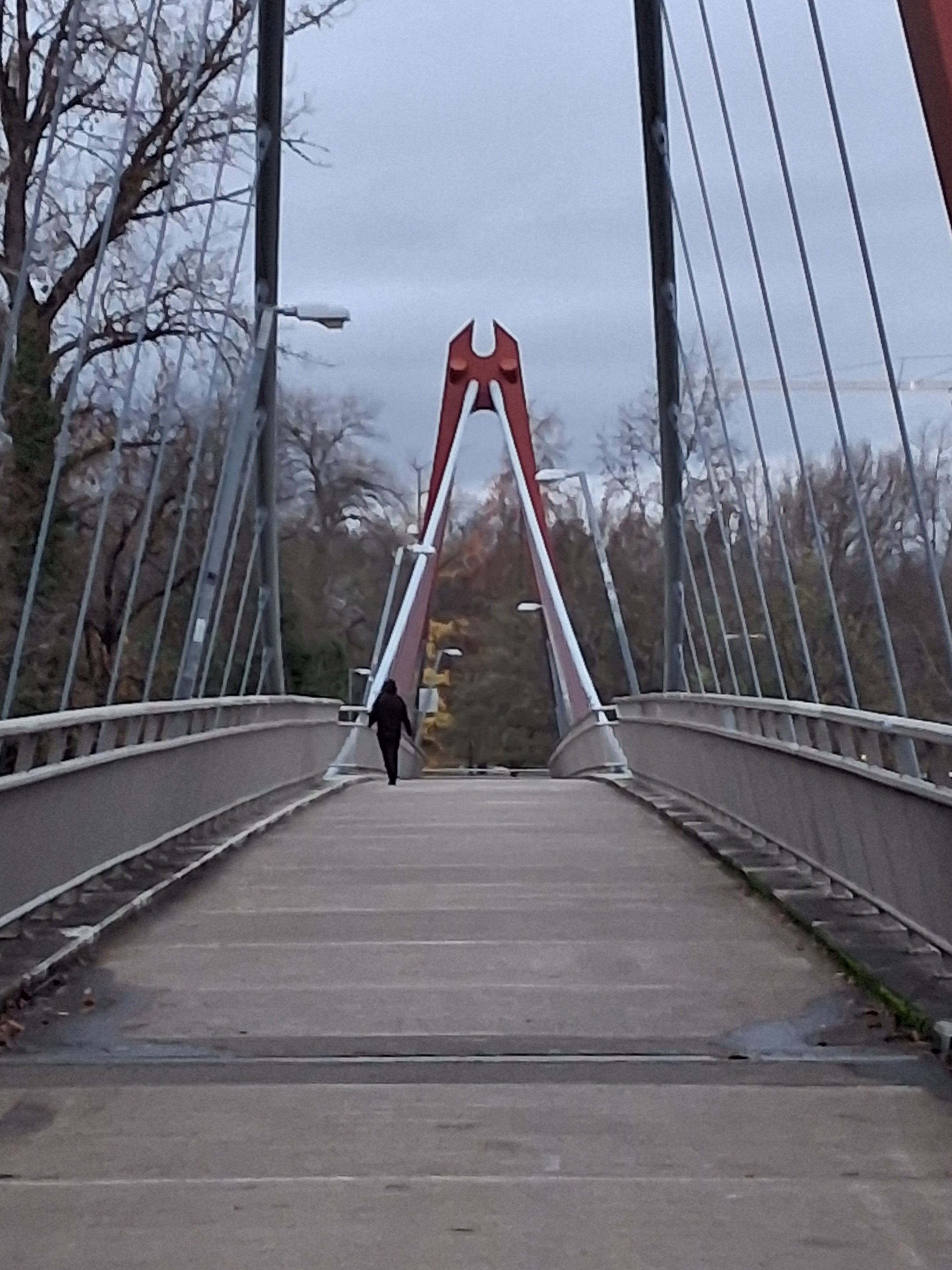
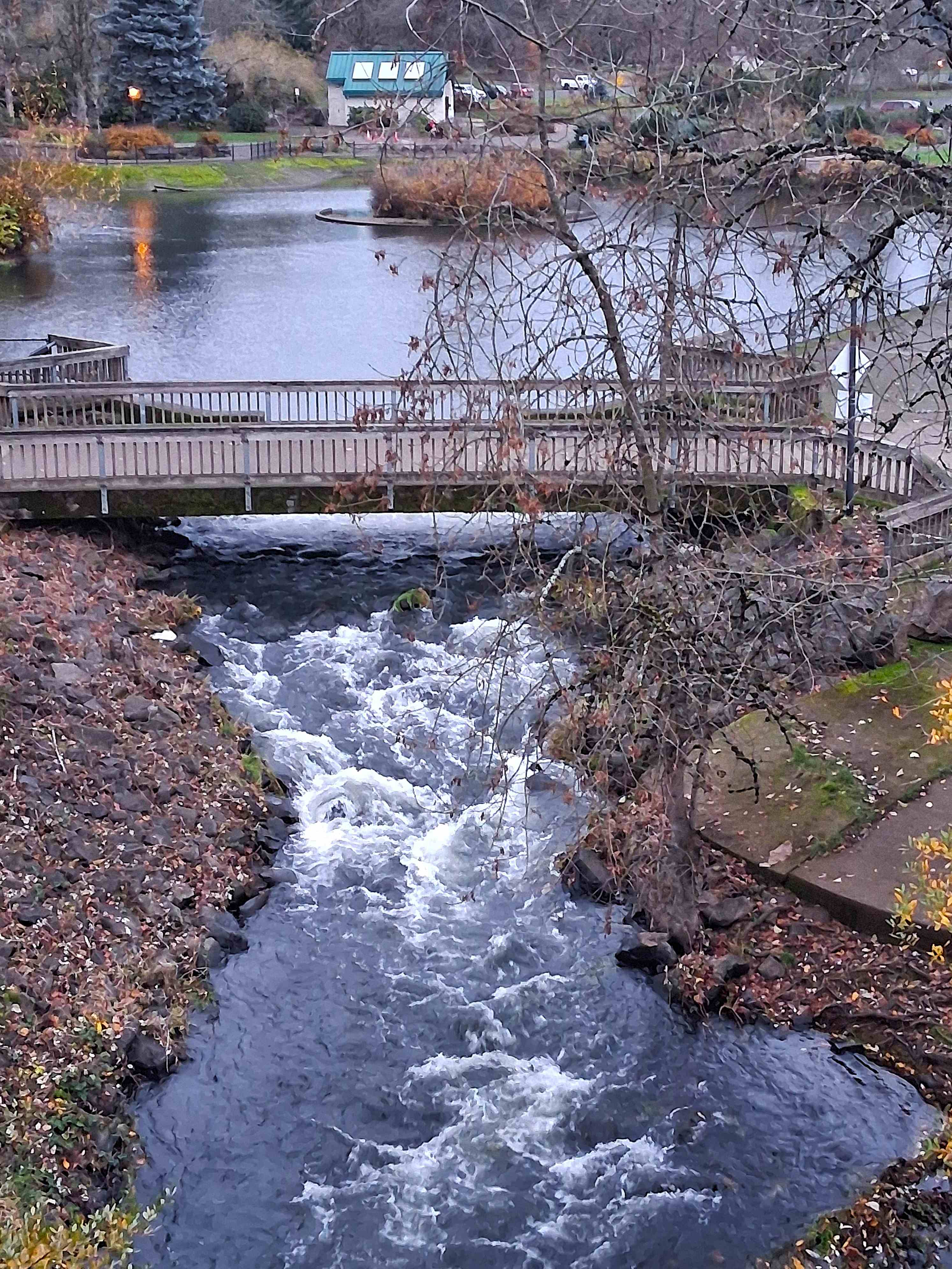
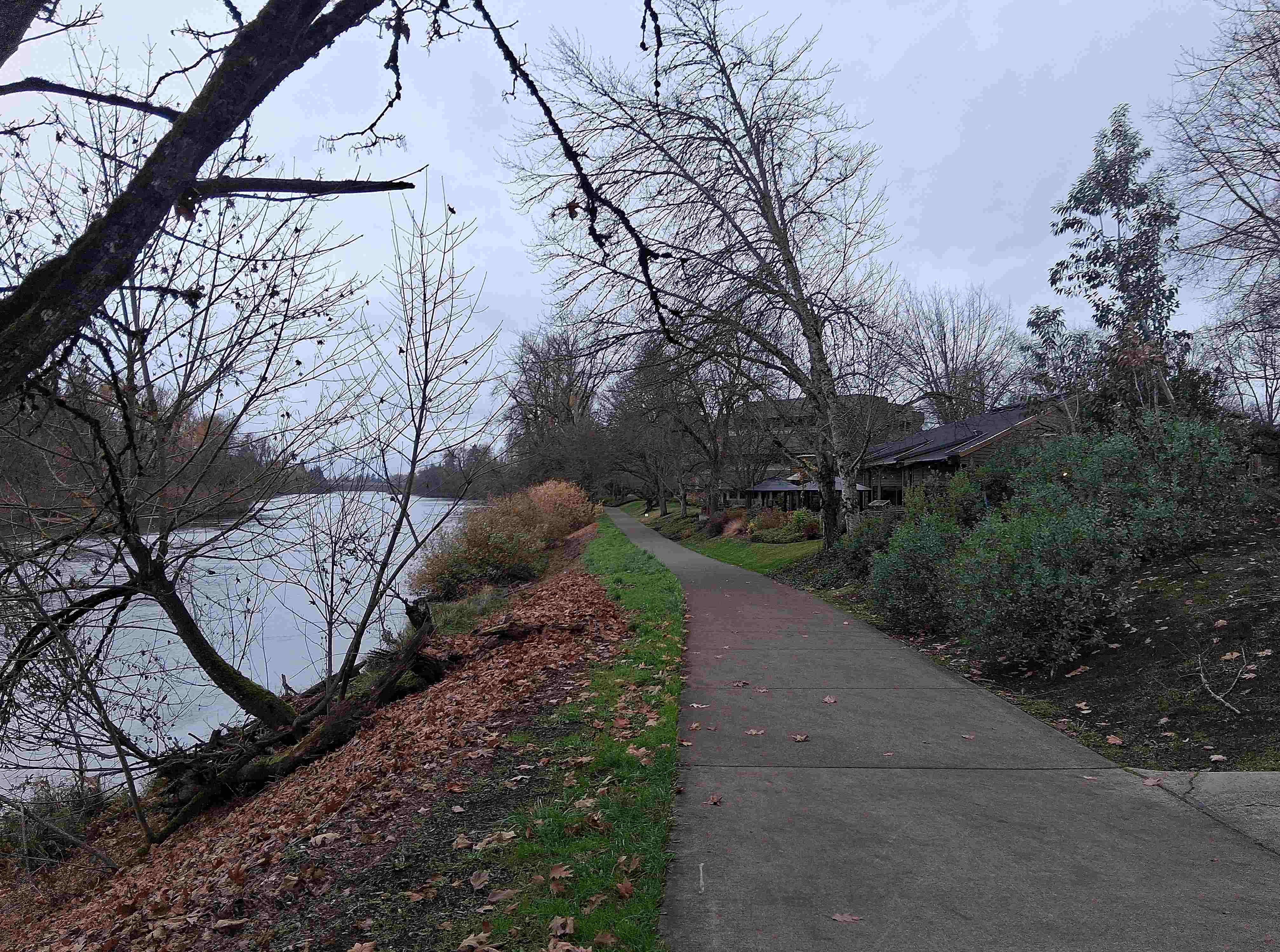
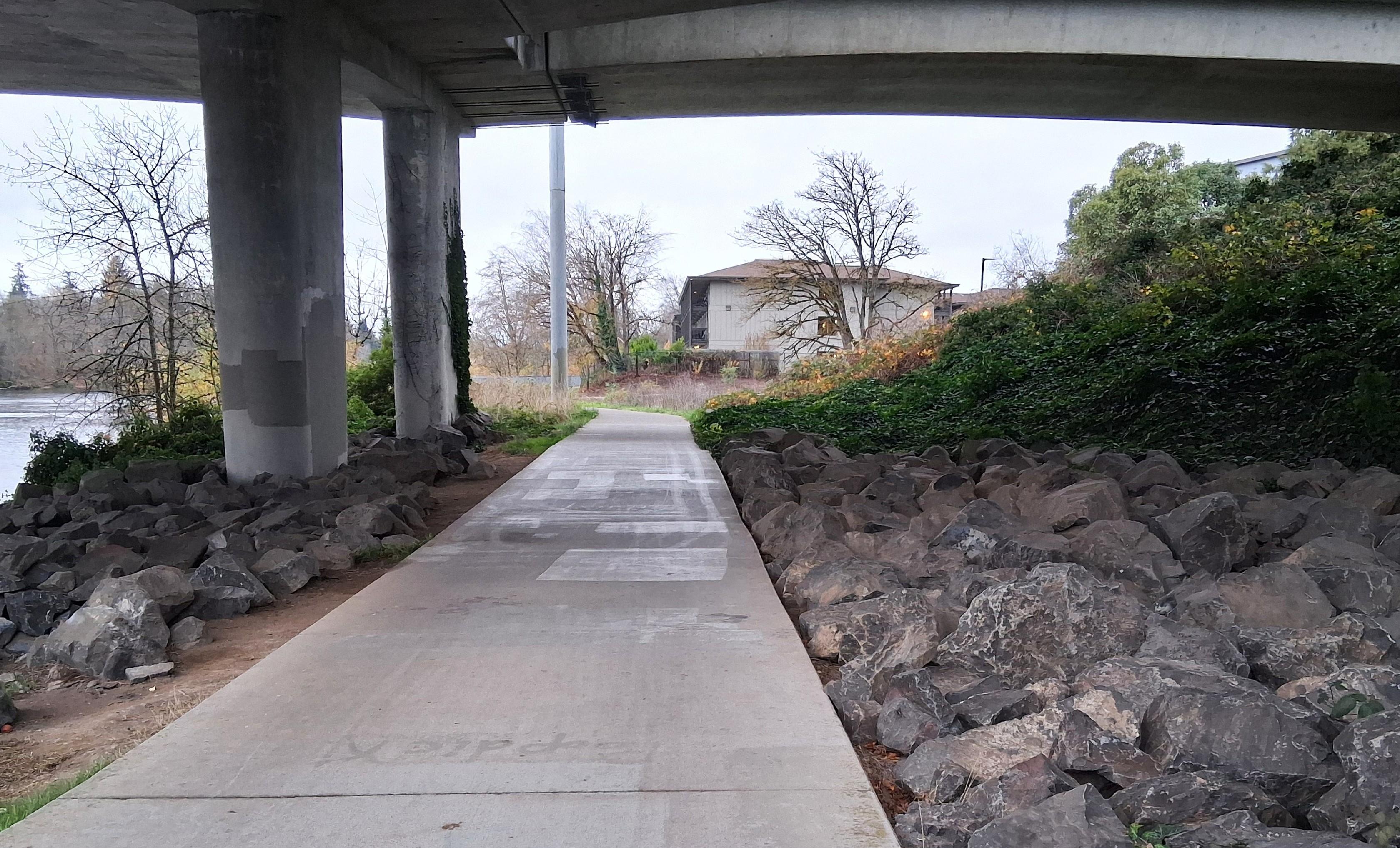
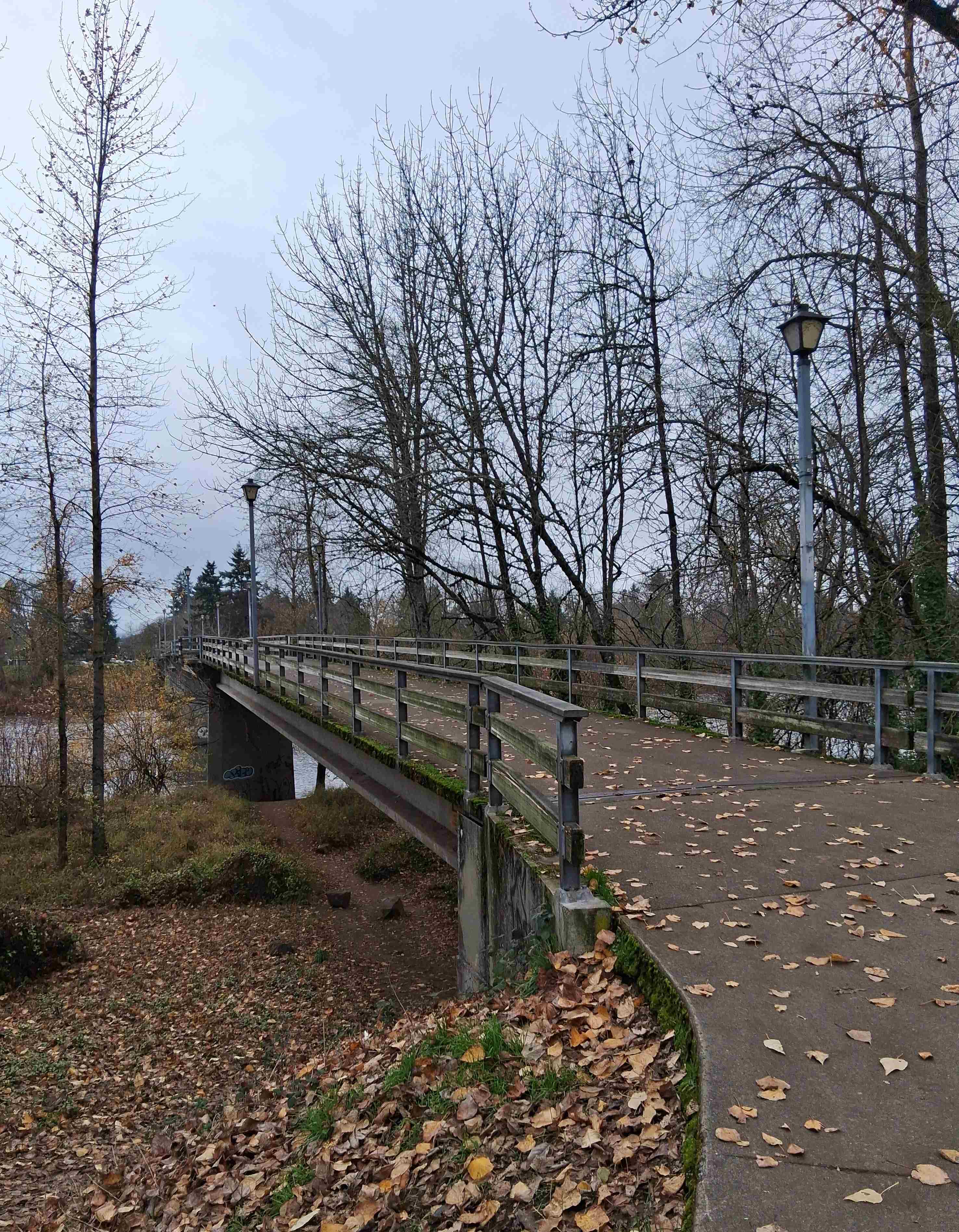
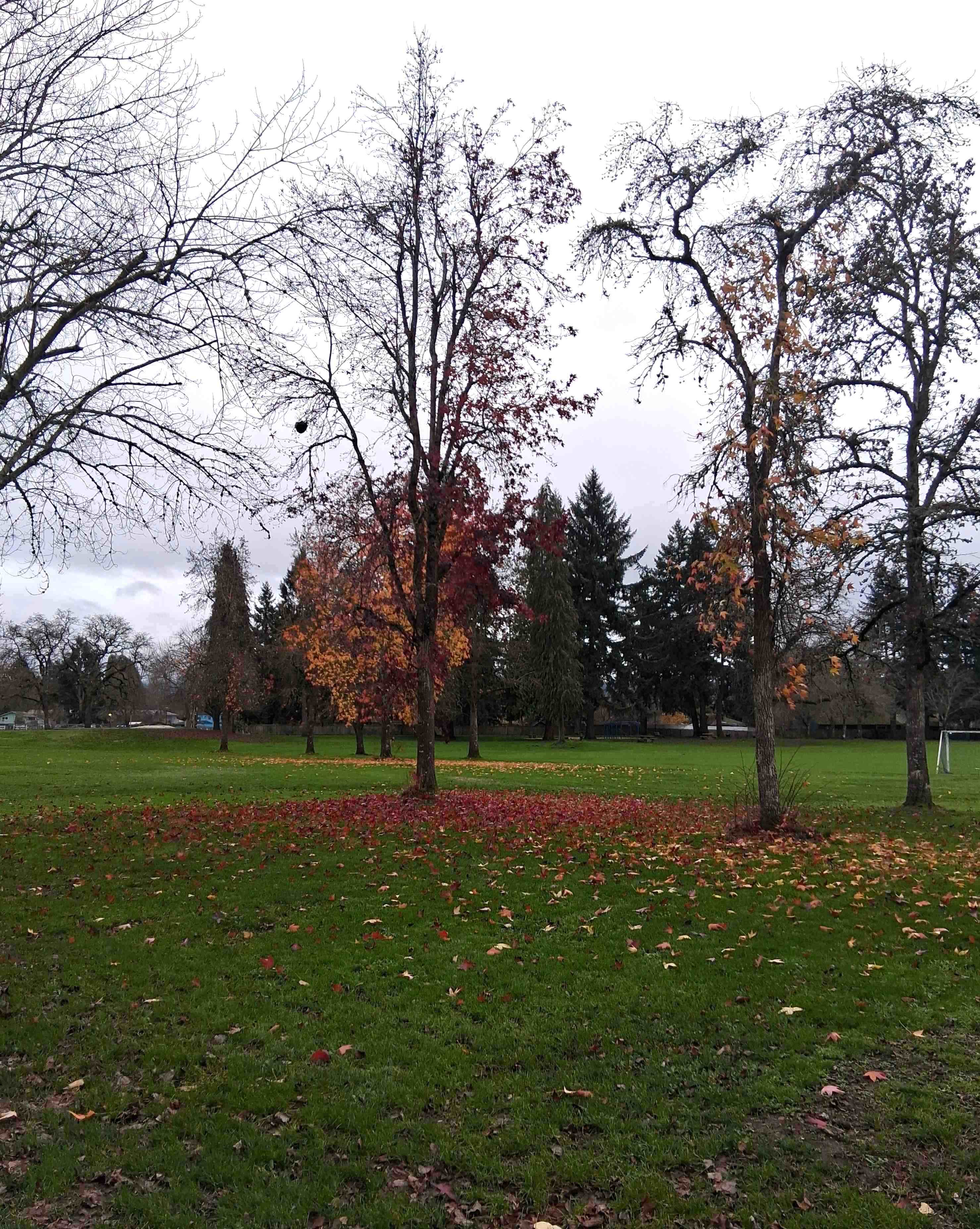
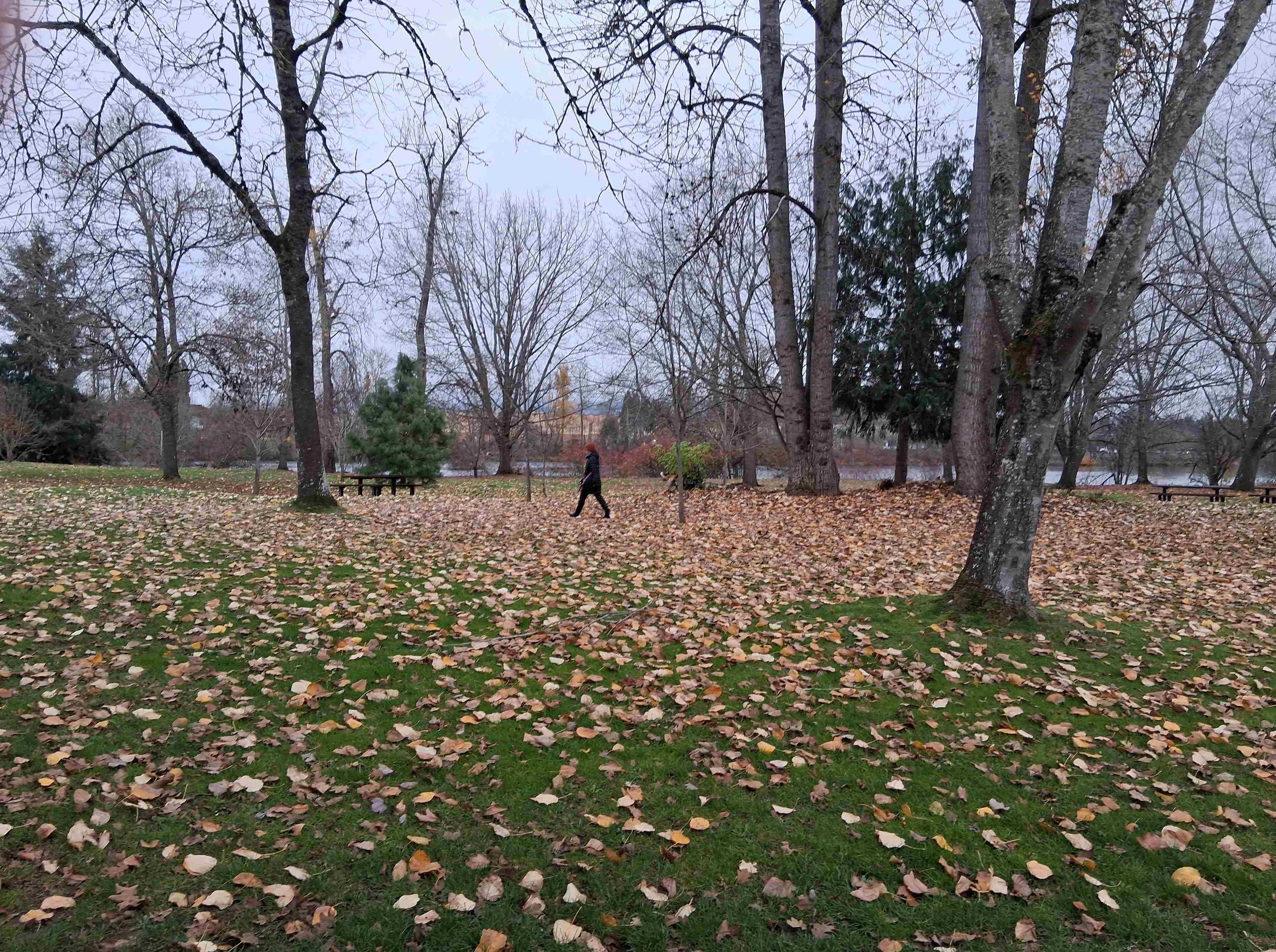
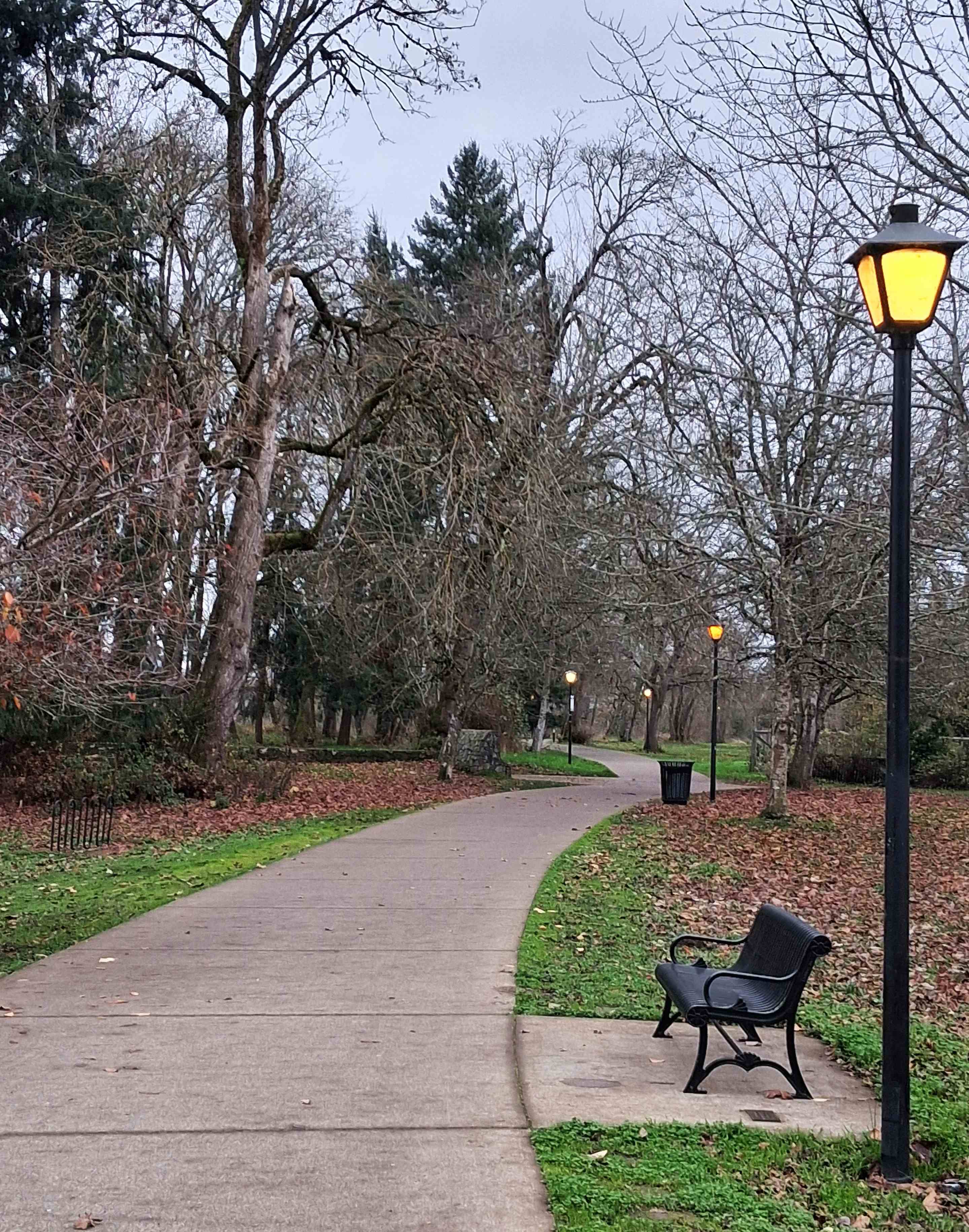
Defazio Bridge Over To Alton Baker ParkAlton Baker Park Lagoon And SpillwayNorth Bank Of The Willamette River Under The Ferry St. BridgeUnder Ferry Street BridgeNorth Bank Trail by McMenaminsUnder I-205 BridgeGreenway BridgeSweetgum Tree Along South Bank TrailMorning WalkTrail Near Eugene Parks Outdoor CenterCedar GroveSouth Bank Trail Toward Skinner Butte
To live content with small means; to seek elegance rather than luxury, and refinement rather than fashion; to be worthy, not respectable; and wealthy, not rich; to study hard, think quietly, talk gently, act frankly… this is my way. (Anonymous)