Category Archives: Woodwork

Hayrake Table – In the Style of Sidney Barnsley

Sidney Barnsley (b.1865-d.1926), was an important and influential Arts and Crafts designer-maker who hand crafted furniture for his family and for clients.  He had previously trained as an architect and worked in London before moving to the rural Cotswolds region of England, Pinbury Park and Sapperton in Gloucestershire.

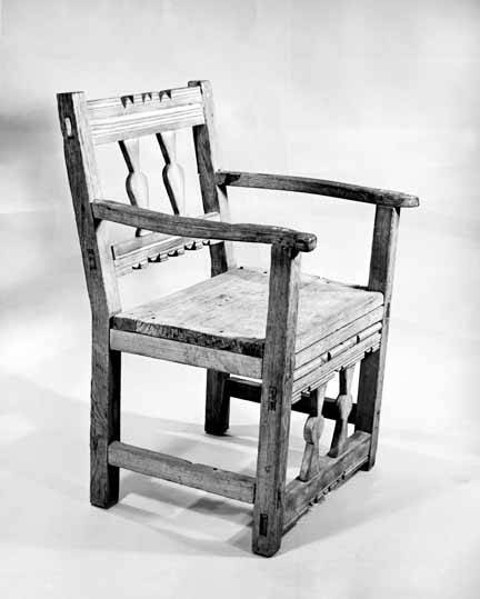
In early 2019, I decided to build an oak dinner table for myself with a leg set that incorporated a “hay rake” or “heel rake” stretcher, a feature that Barnsley had adapted for one of his tables from a traditional wooden rake used by farmers to rake hay in their fields into windrows.  Below is a photo of one of these 18th~19th century rakes showing the joinery used to create the handle.  It is a marvel of traditional, rural woodworking that is very strong but lightweight . . . a perfect example of form following function.  [Click on any image to enlarge.]

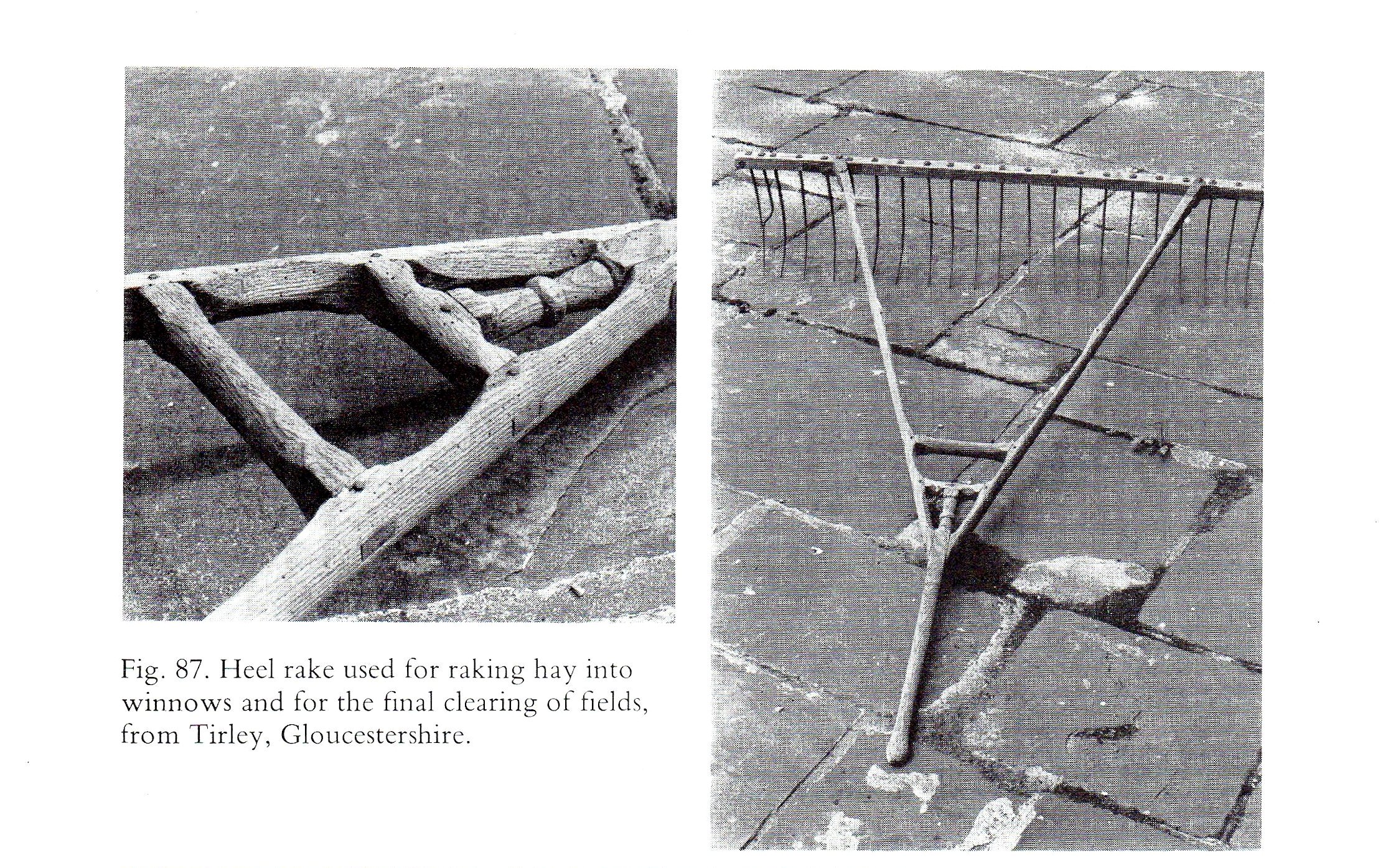
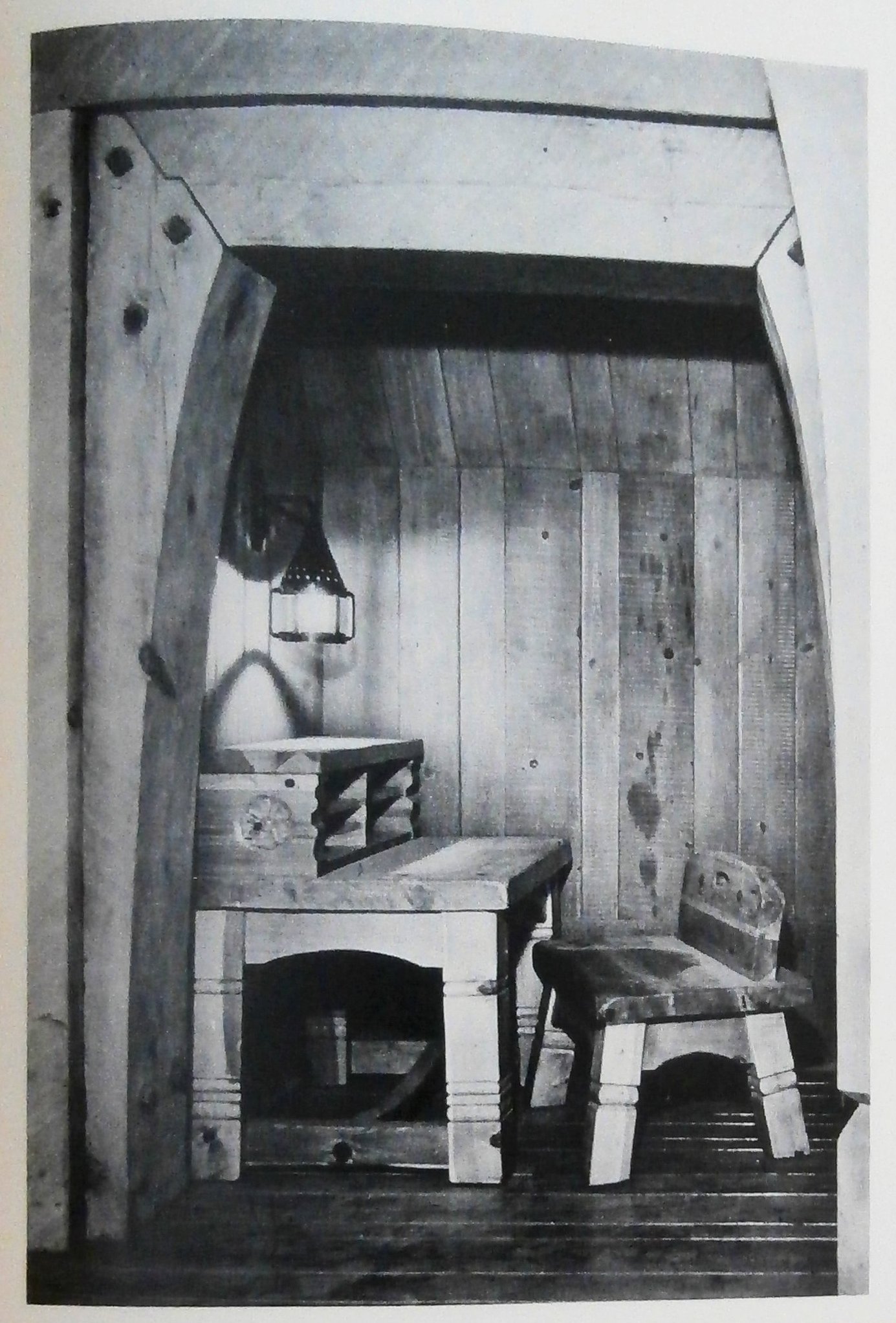
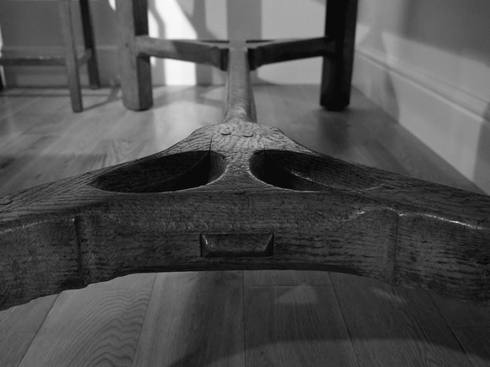
Barnsley used the essentials of the rake joinery to create the stretcher (see below) for his table, circa 1900.  All three b&w photos are taken from Gimson and the Barnsleys by Mary Comino (Van Nostrand Reinhold Co., 1980).

Sidney Barnsley: hay rake table
Sidney Barnsley: hay rake joinery

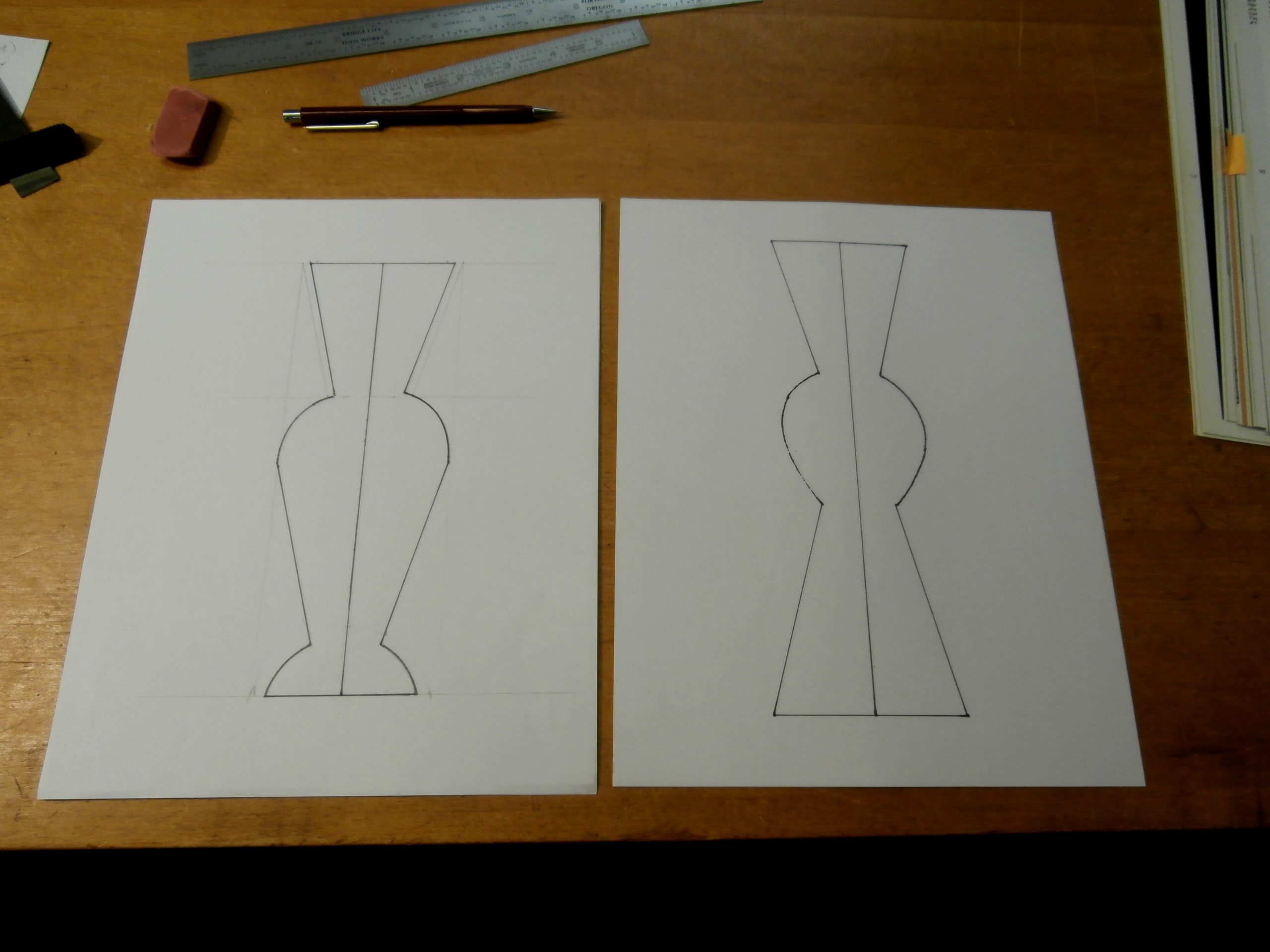
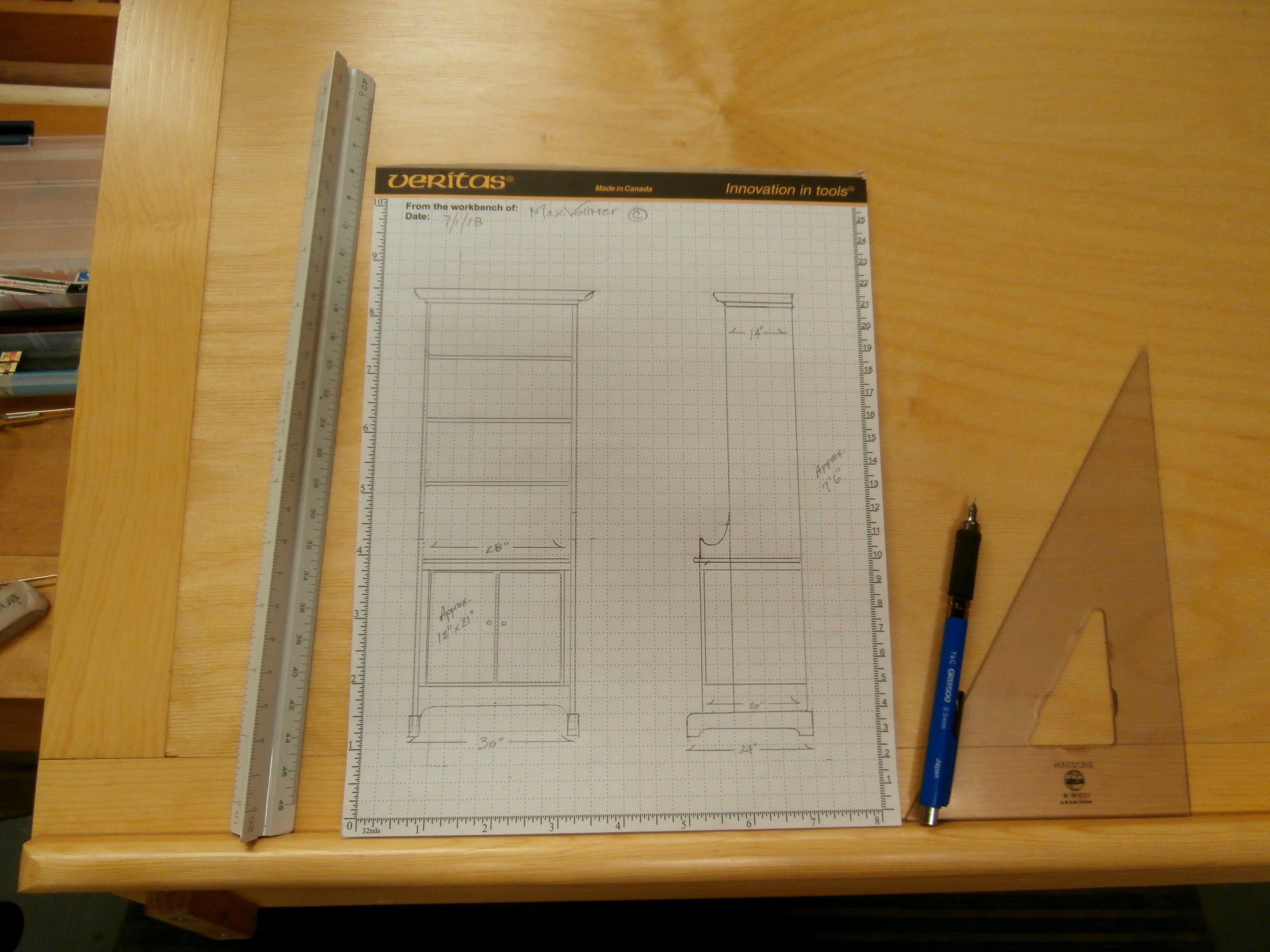
With no original drawings to go by, I made my own full size, scaled plans and set to work on the “Y” shaped joint only to find that my first effort was not going to be satisfactory.  It ended up going in my wood stove.  I revised the plans based on my experience and started over.  [Click on any image to enlarge.  All following photos copyright symbol Max Vollmer]

Revised plans.

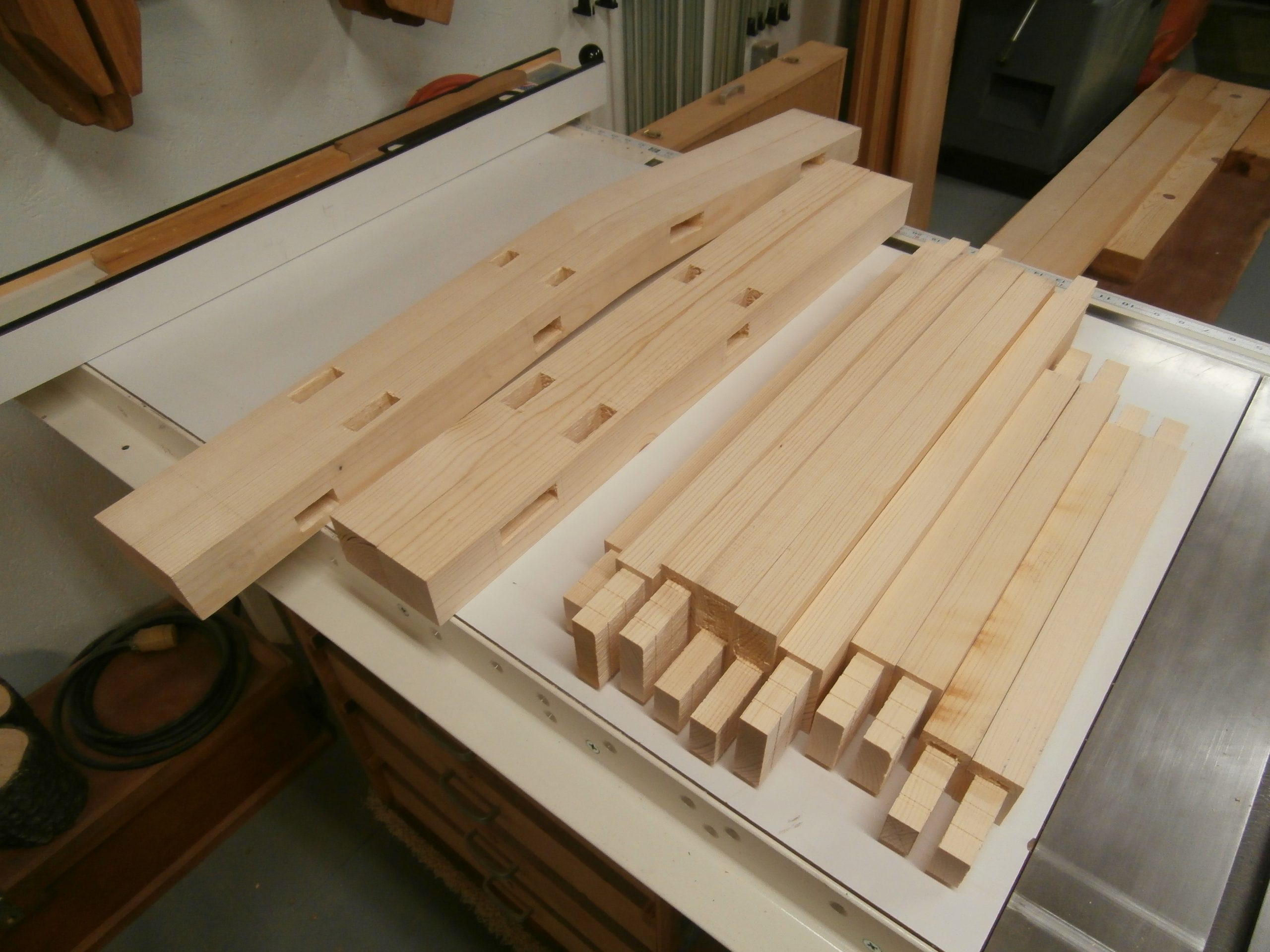
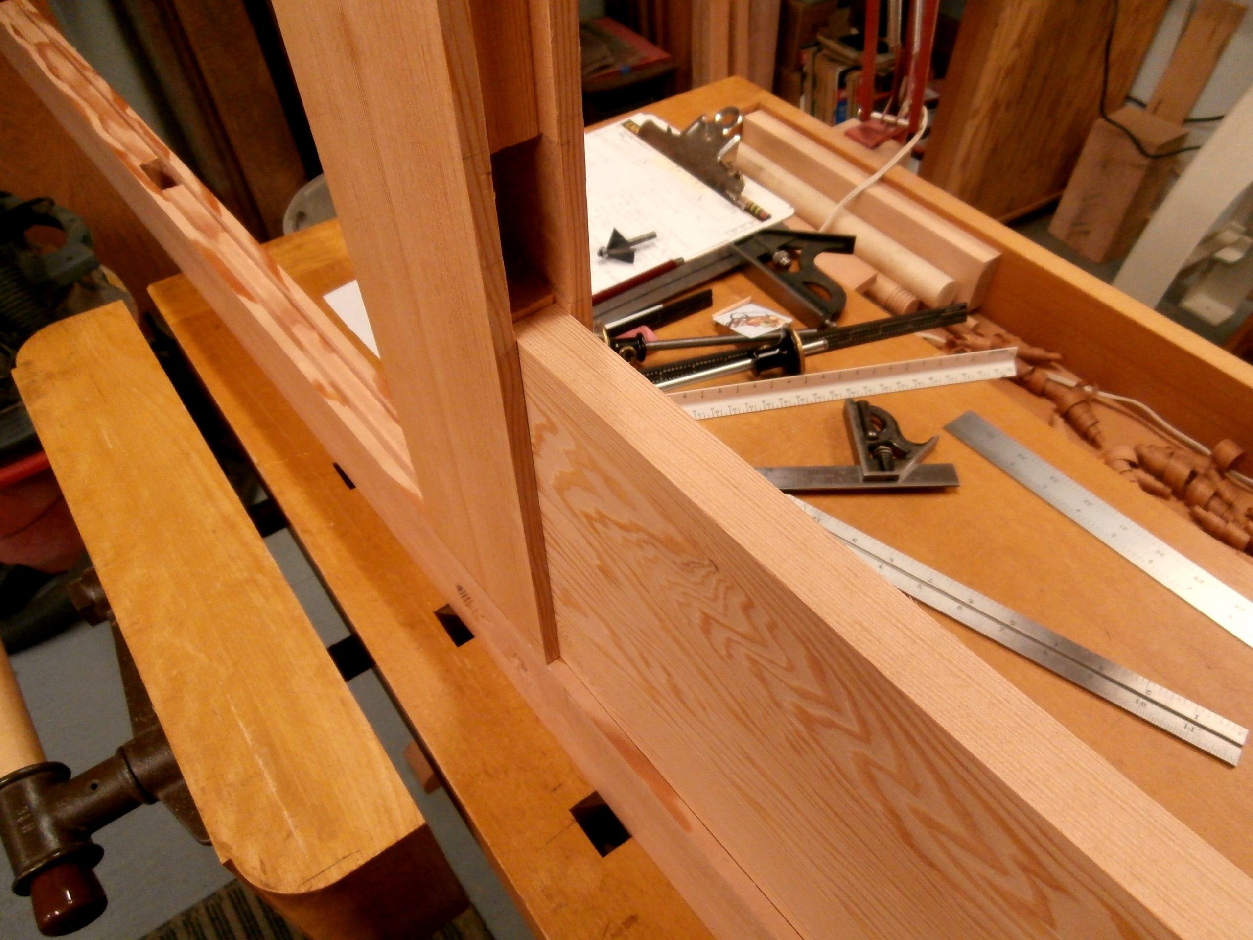
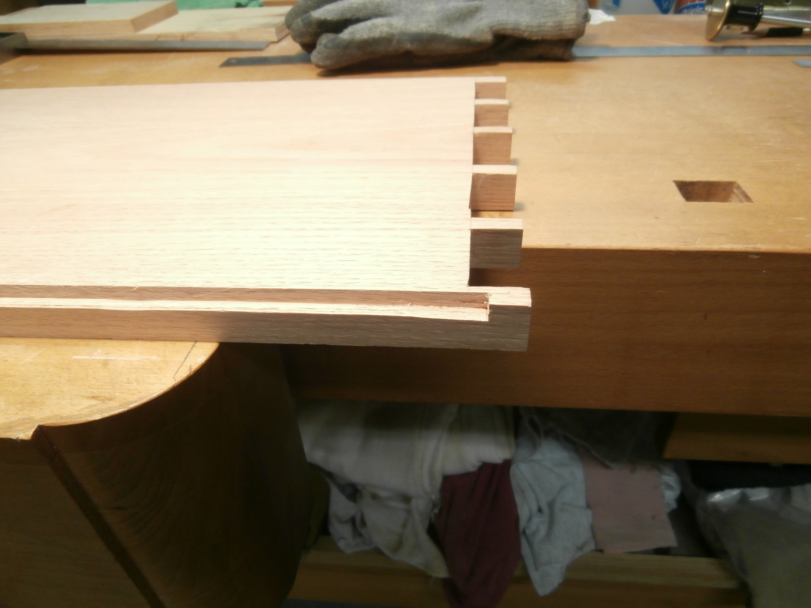
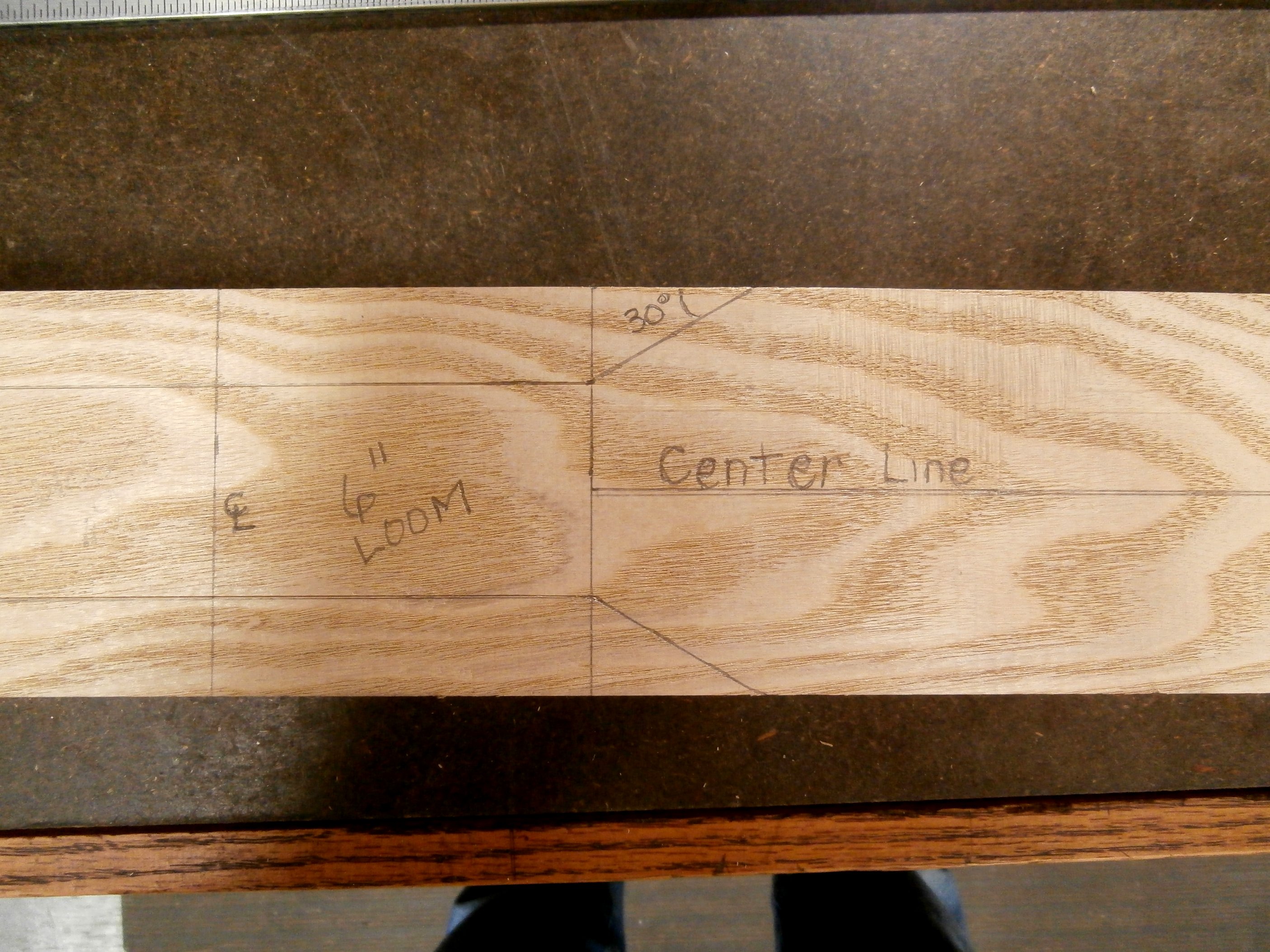
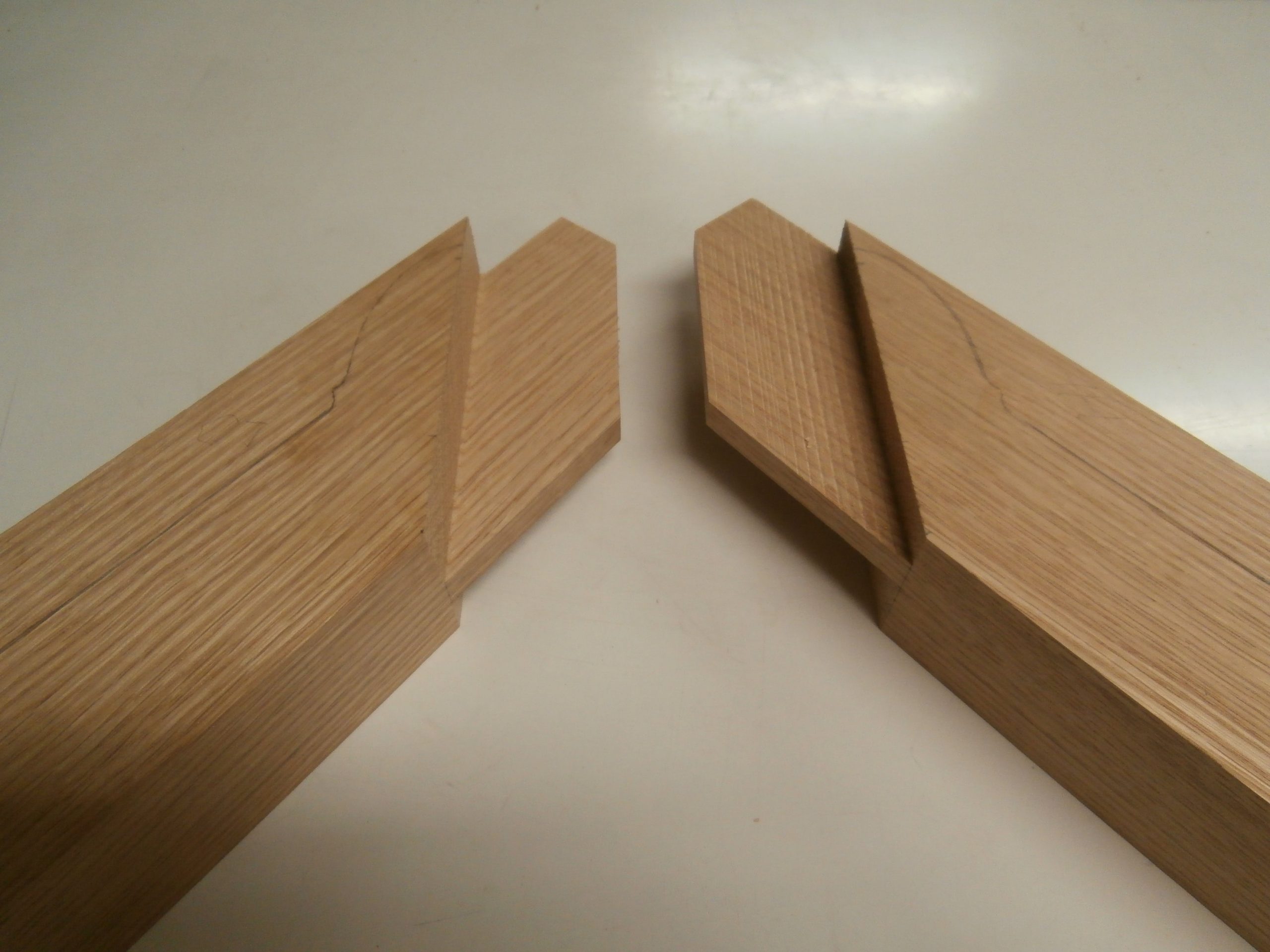
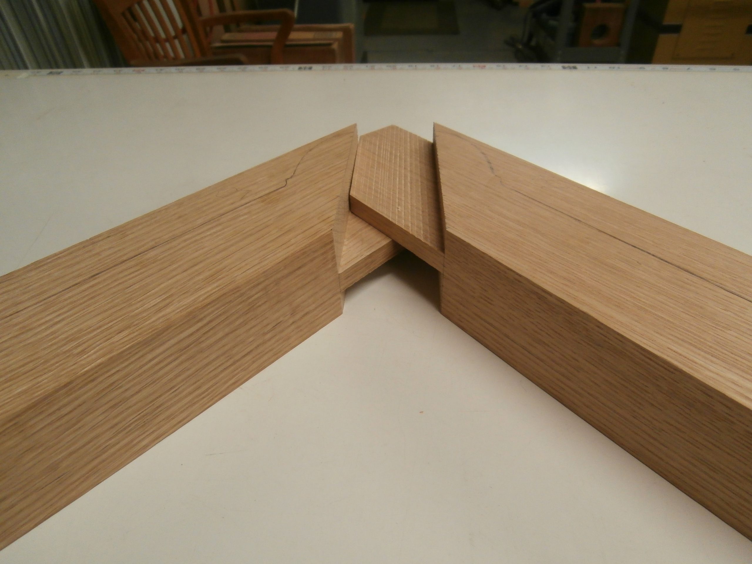
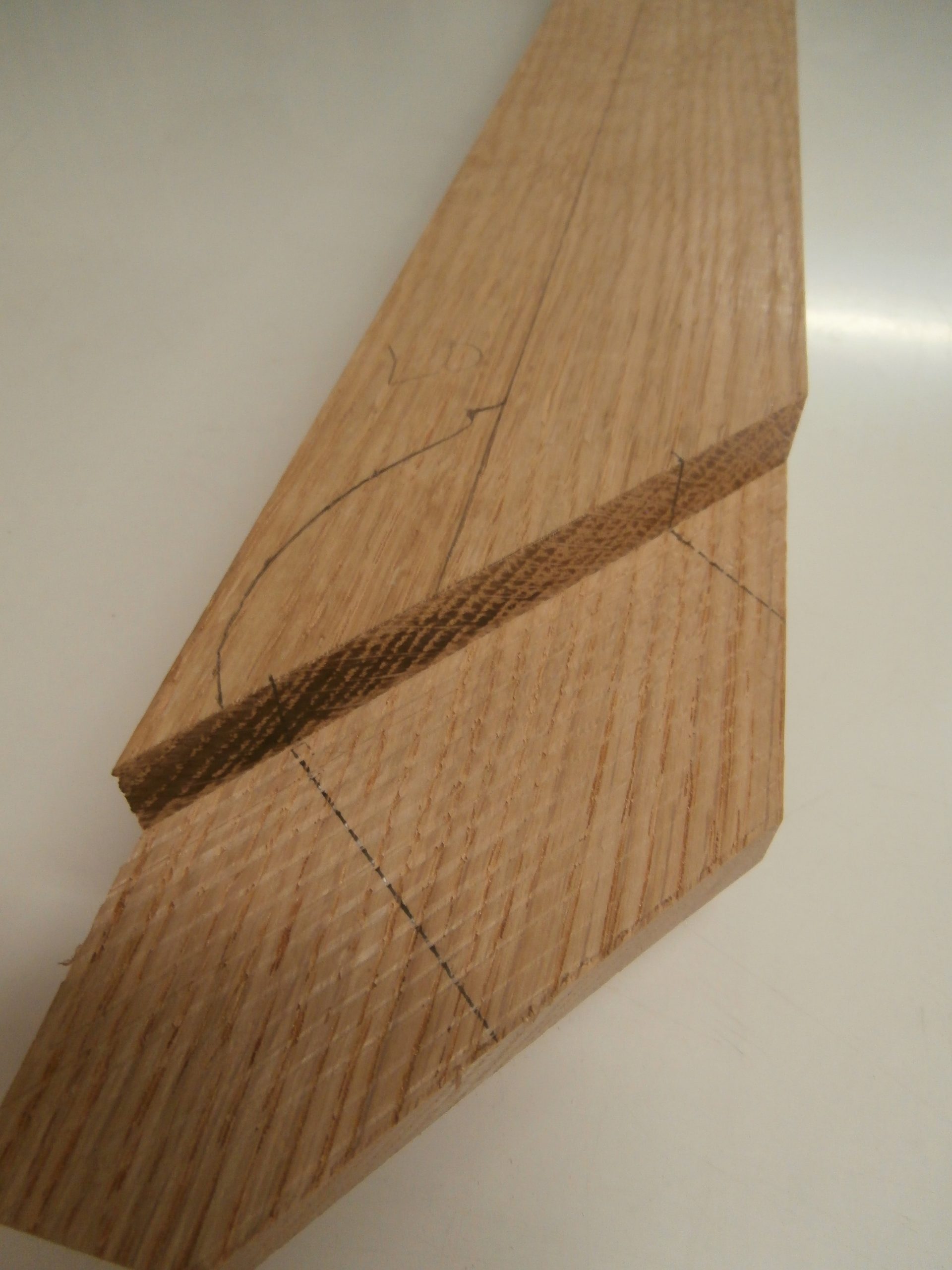
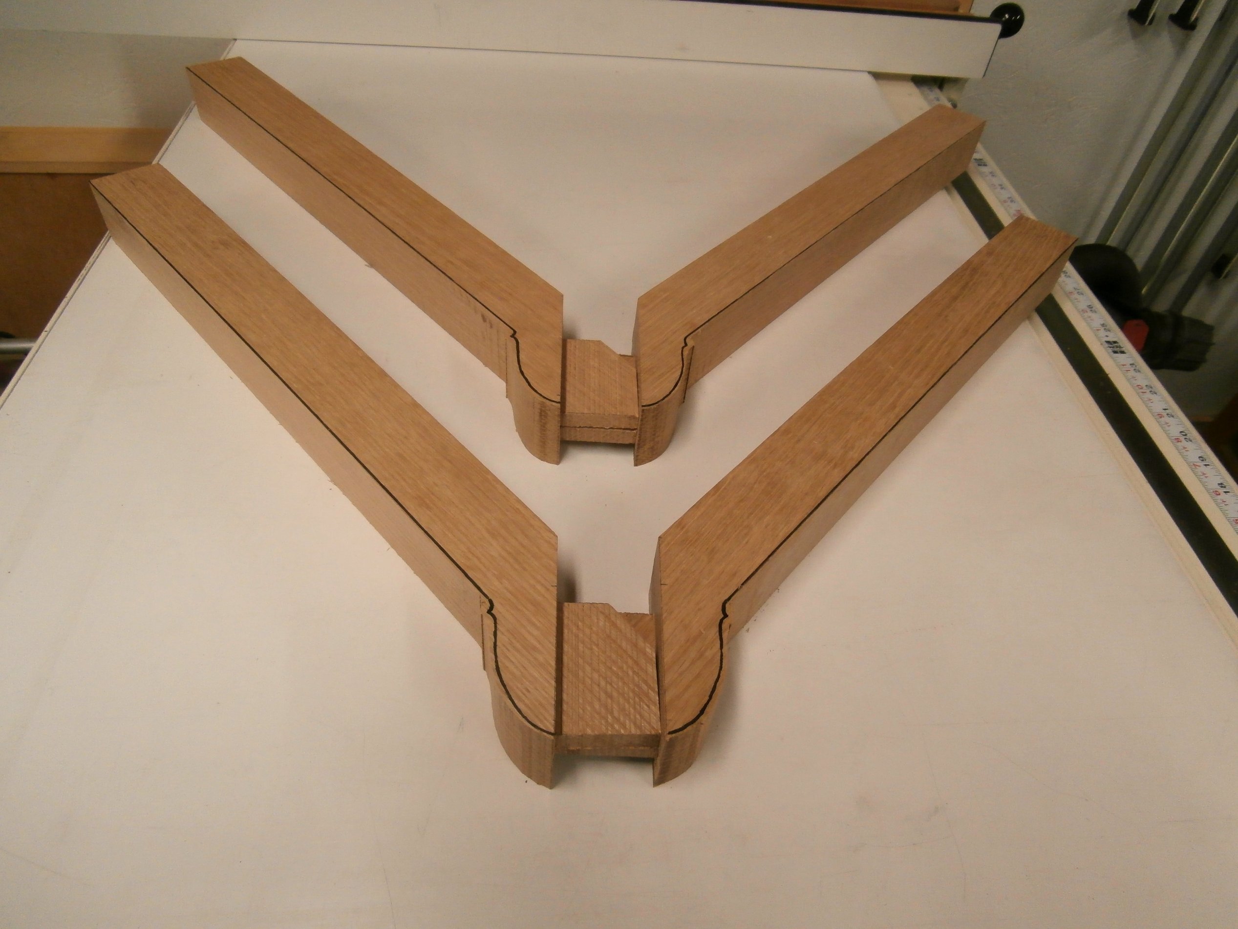
For aesthetic reasons I reduced the acute angle between the arms of the “Y” and the main, longitudinal stretcher from 45 degrees to 40 degrees.  I used overlapping tenons on the arms where they intersect and join the main stretcher.

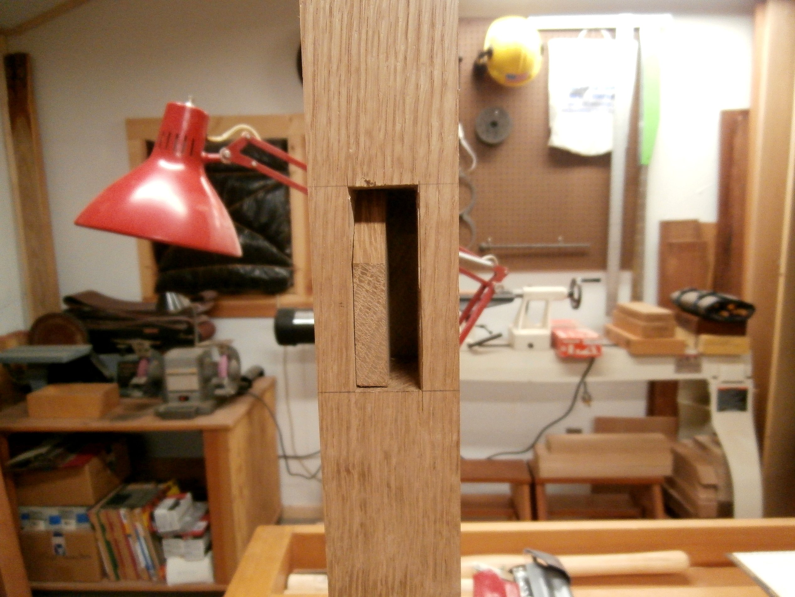
And, based on my first failed effort, I also redesigned the tenons on the “spanner” or brace that connects the two arms of the “Y.”  This allowed me to cut “through” mortises in the arms that were perpendicular to the axis of the arms rather than  mortises cut at a 40 degree angle.  This way I could use straight tenons on the spanner.  Not only was this redesign equally strong, it was much easier to cut the mortises. The following series of photos illustrate my approach.  [Click on any image to enlarge, All photos copyright symbol Max Vollmer]

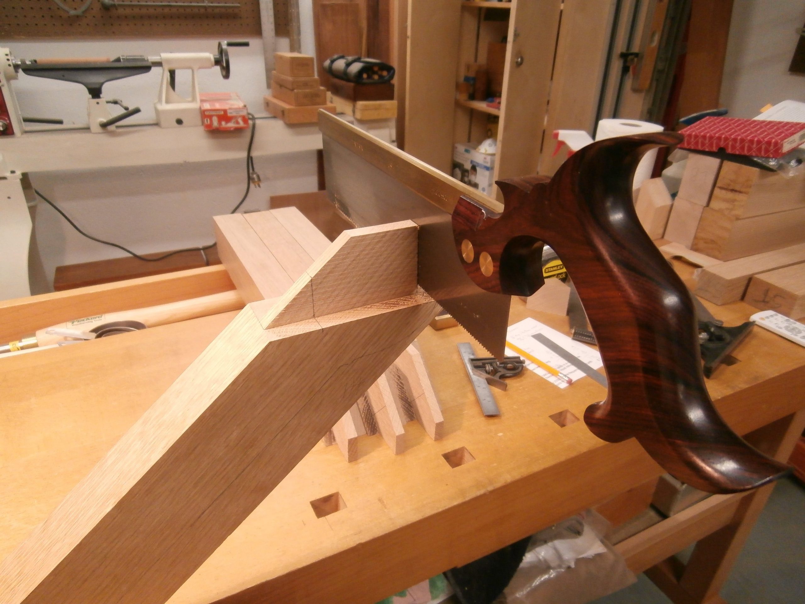
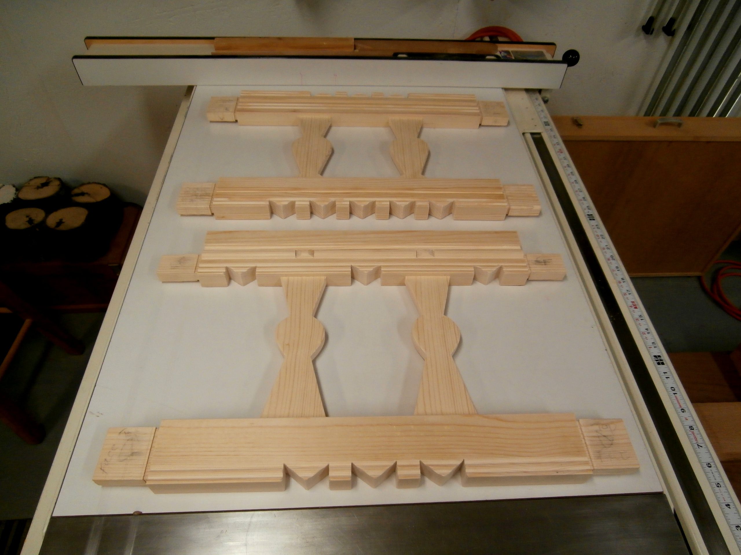
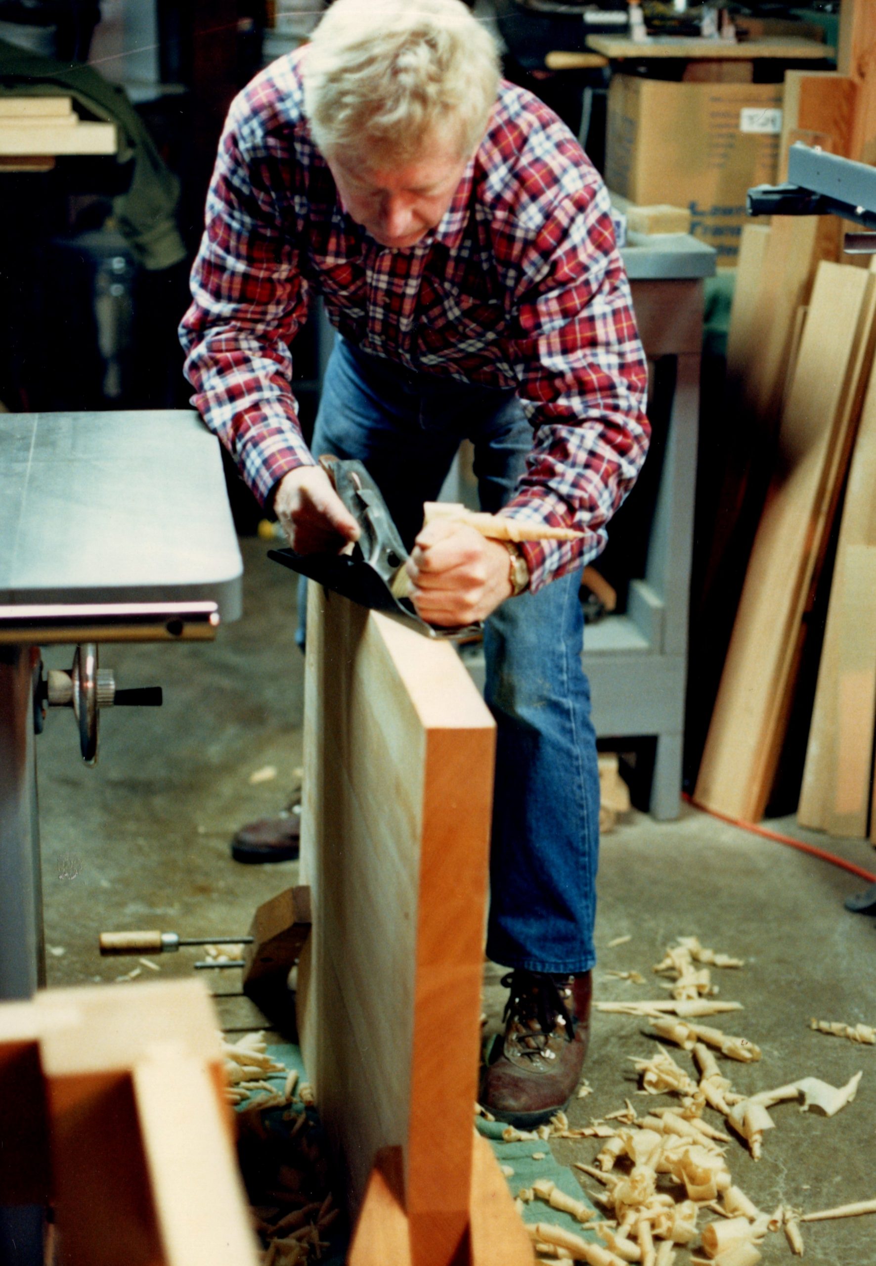
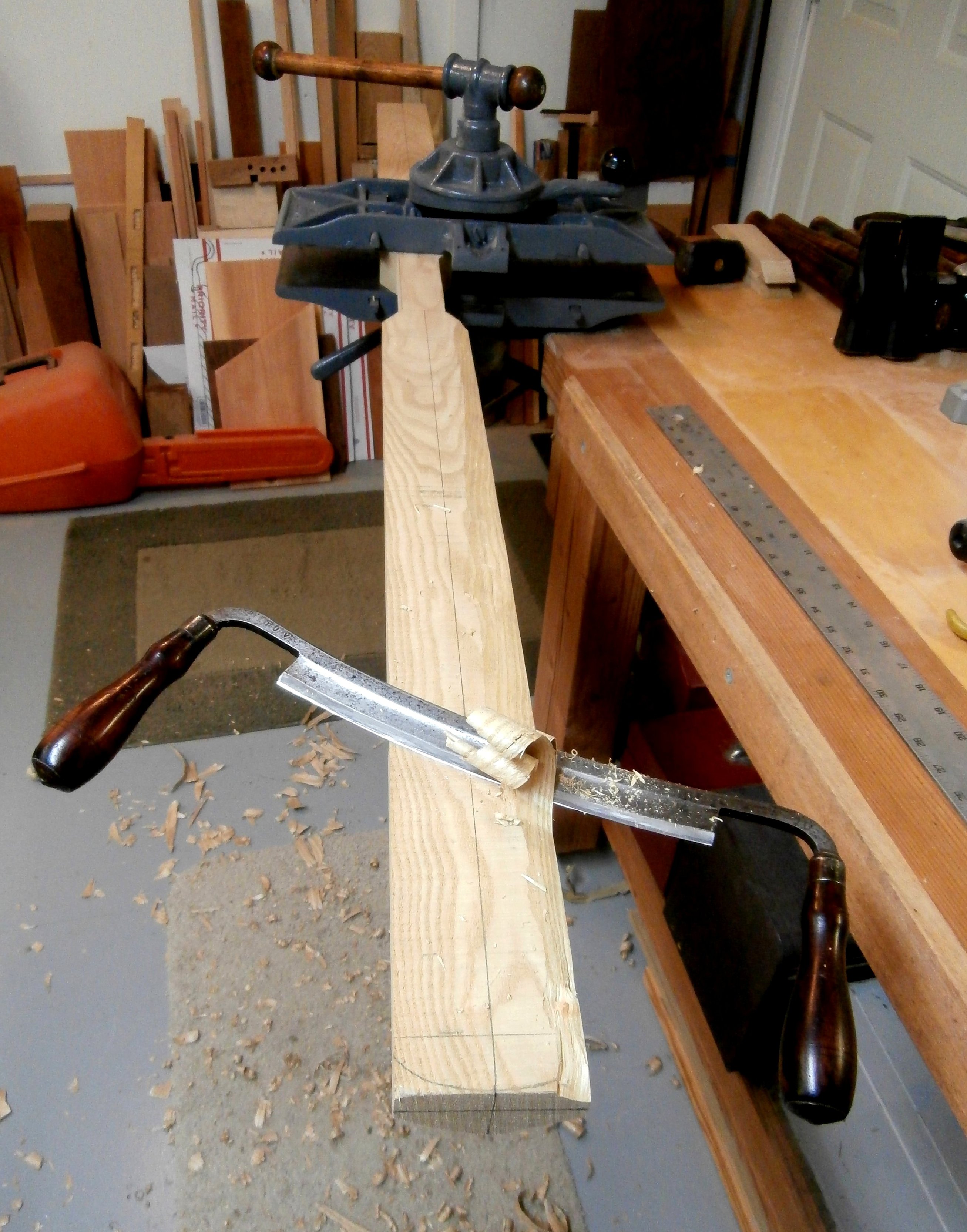
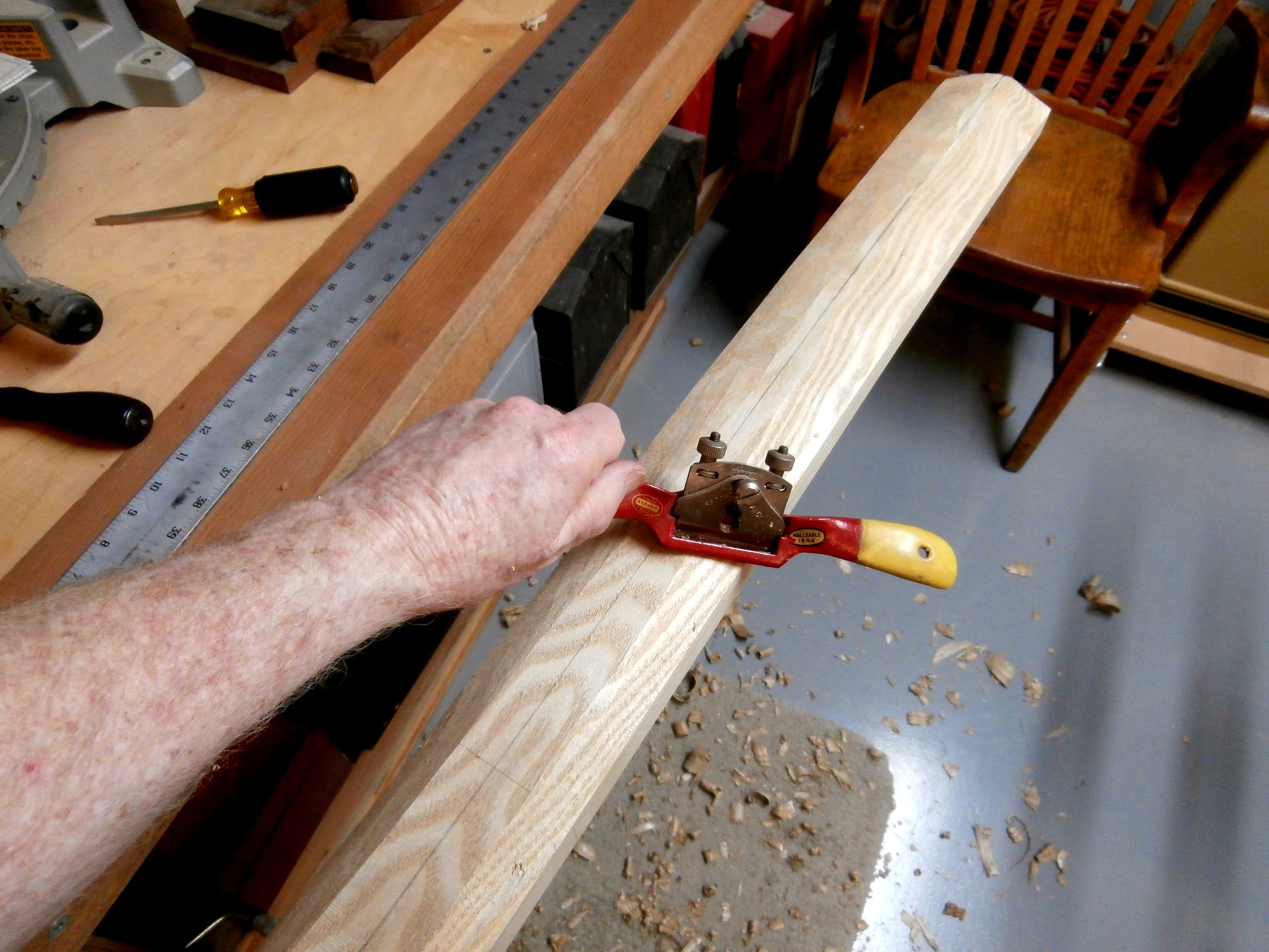
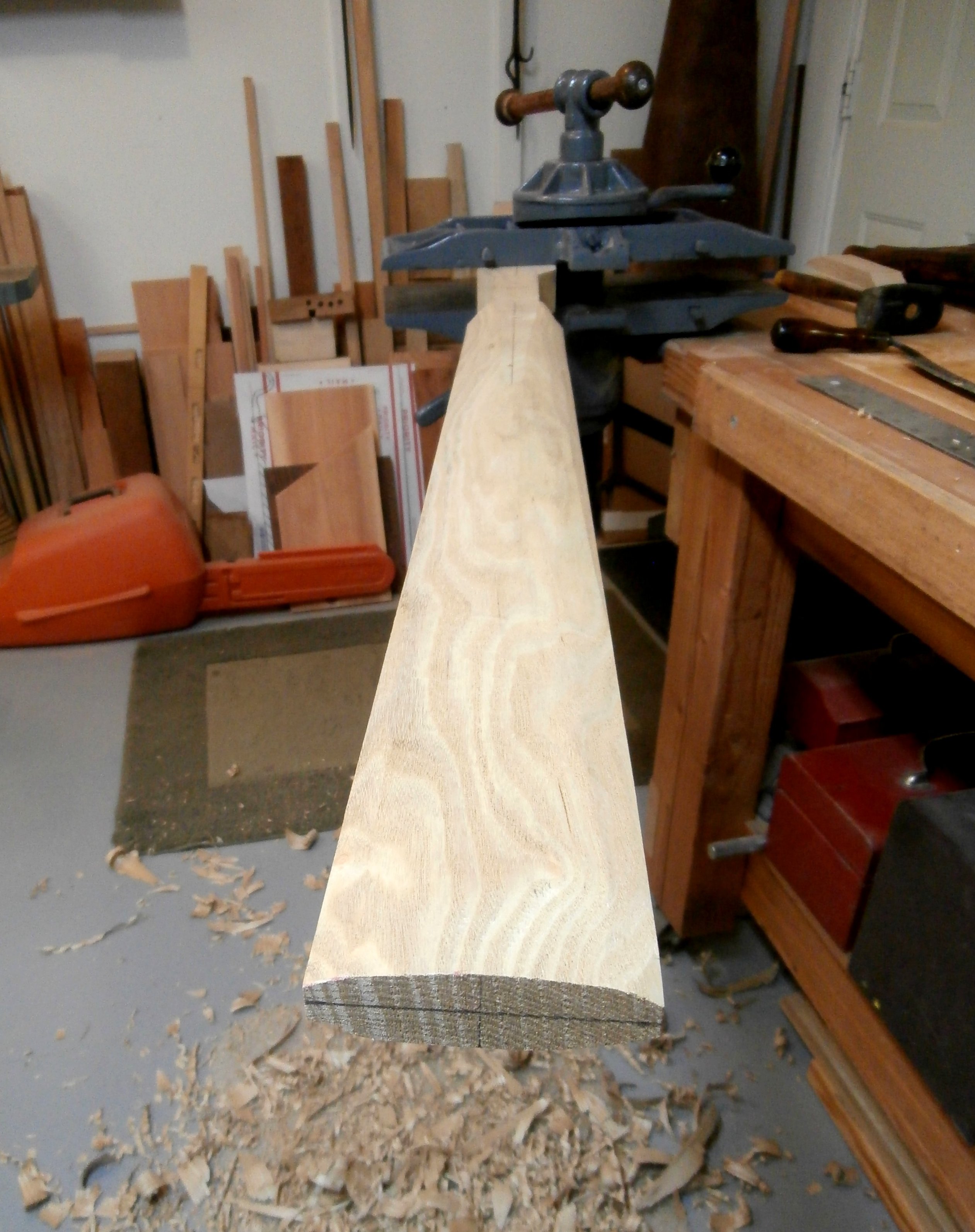
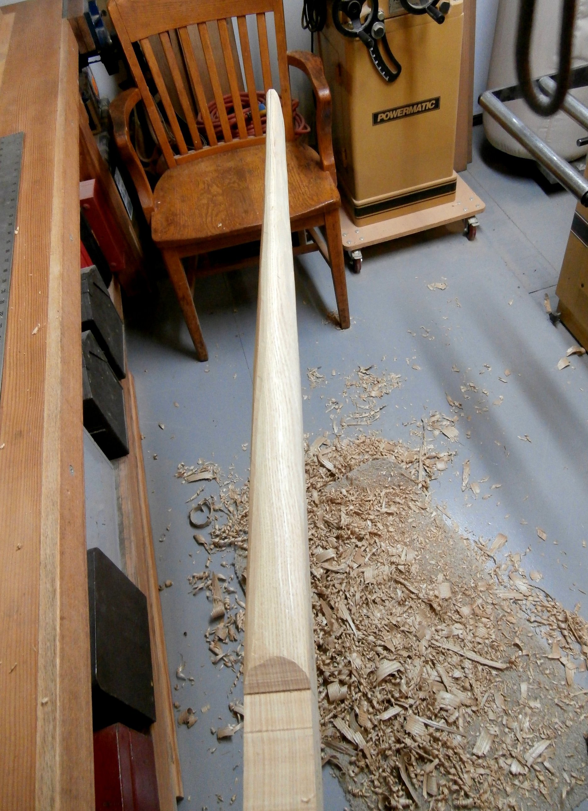
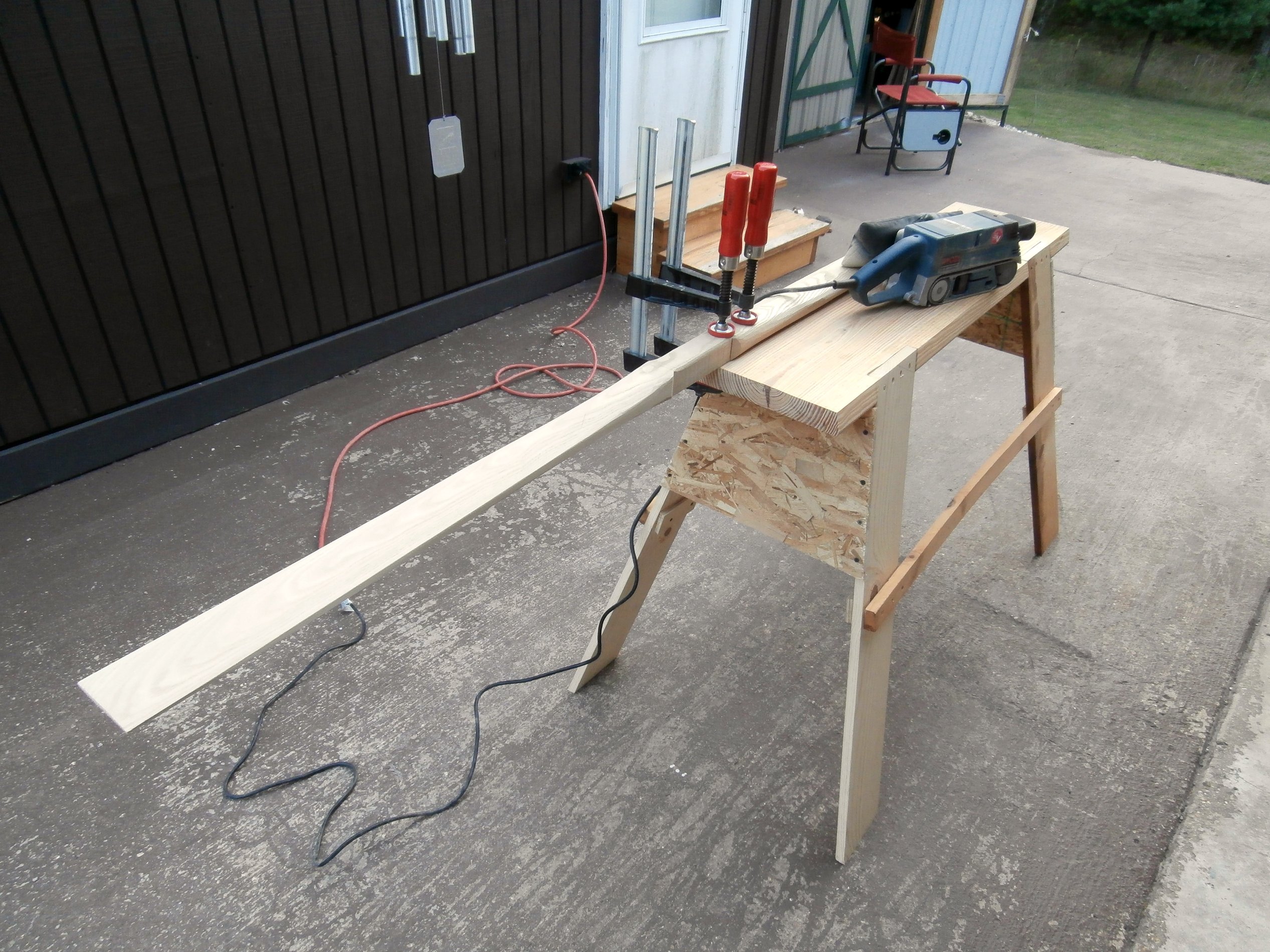
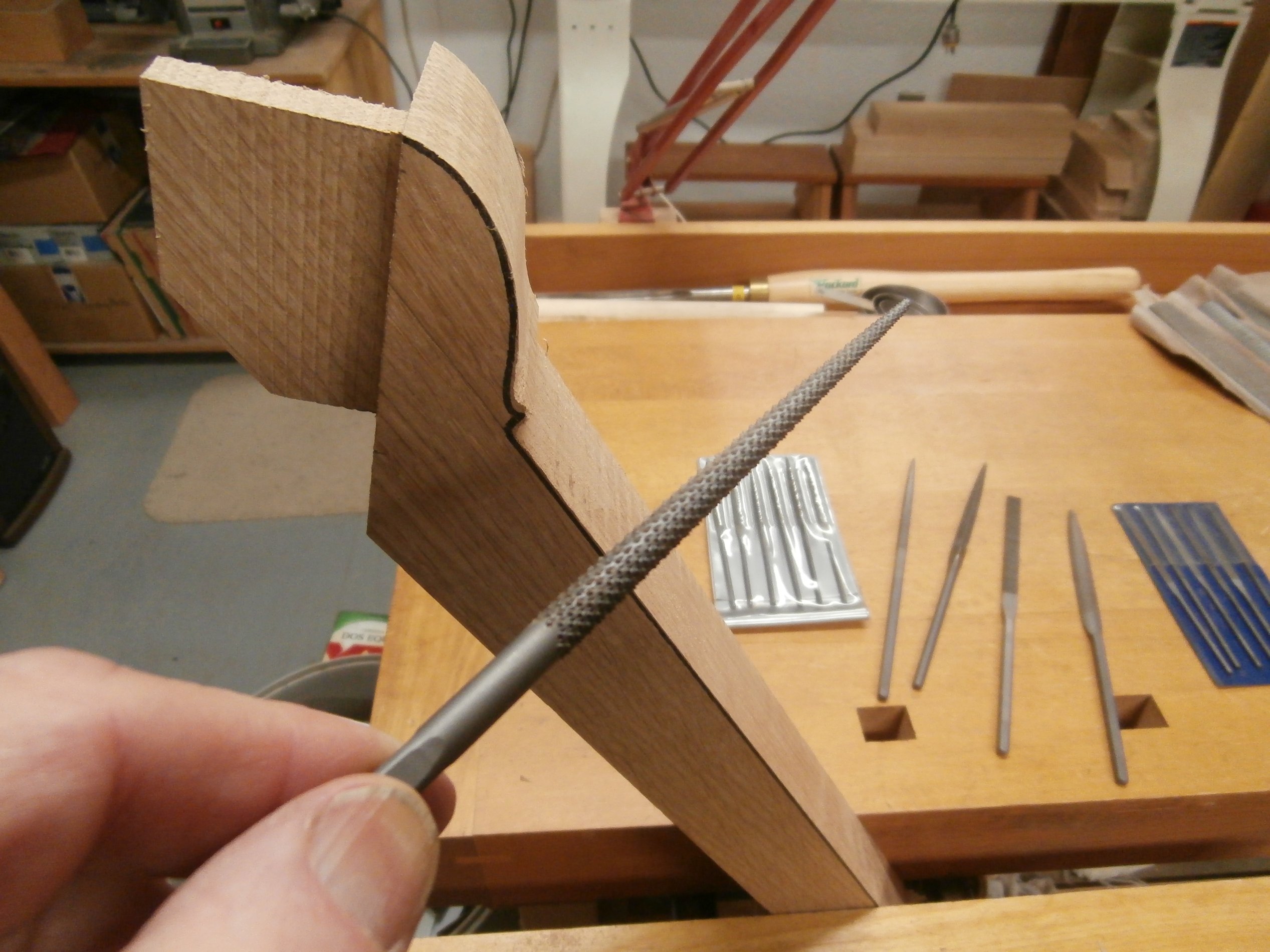
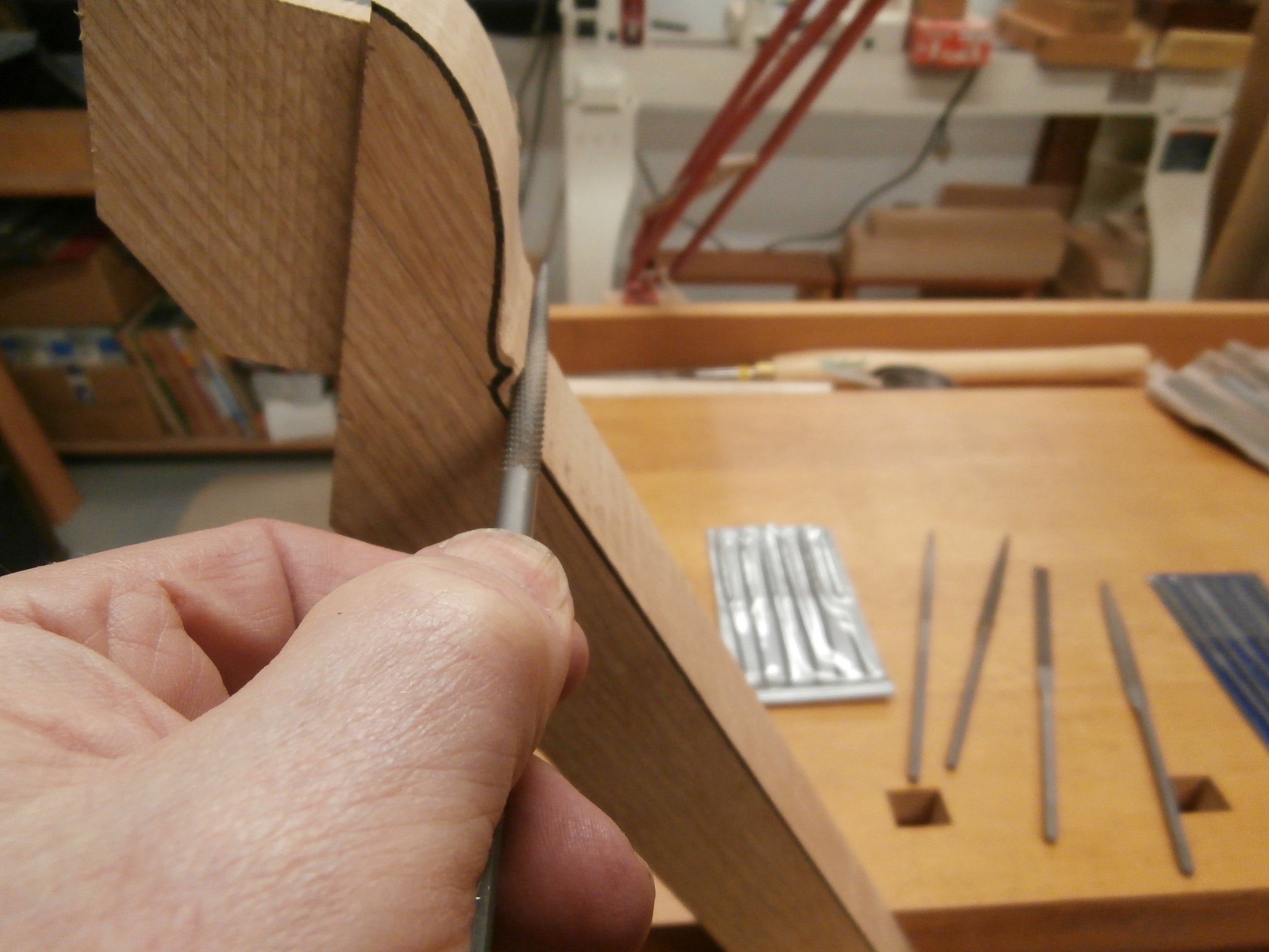
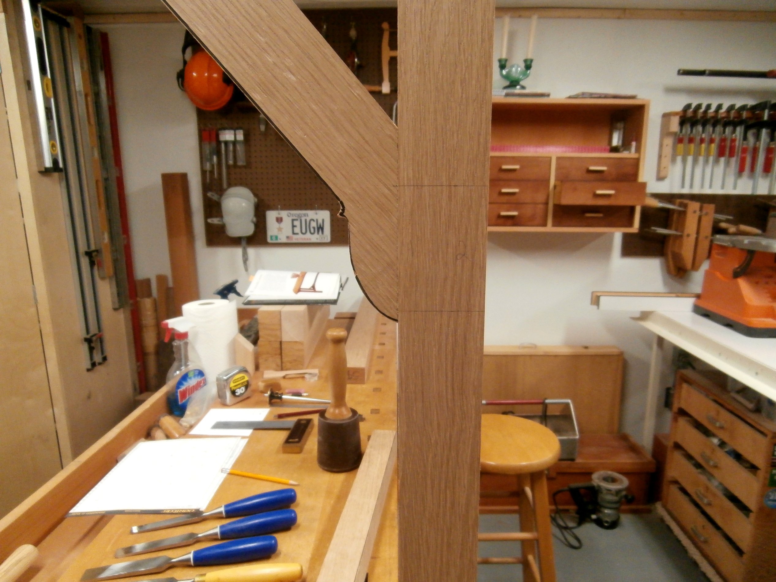
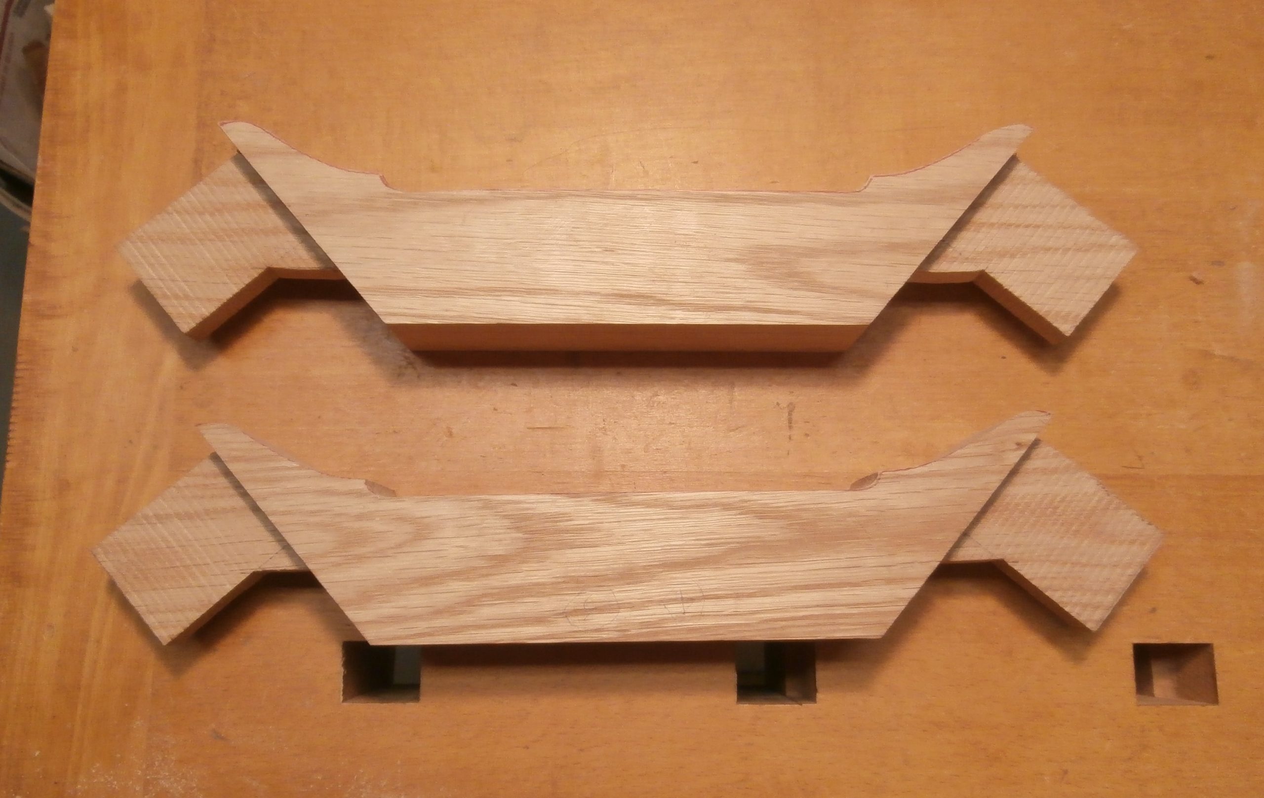
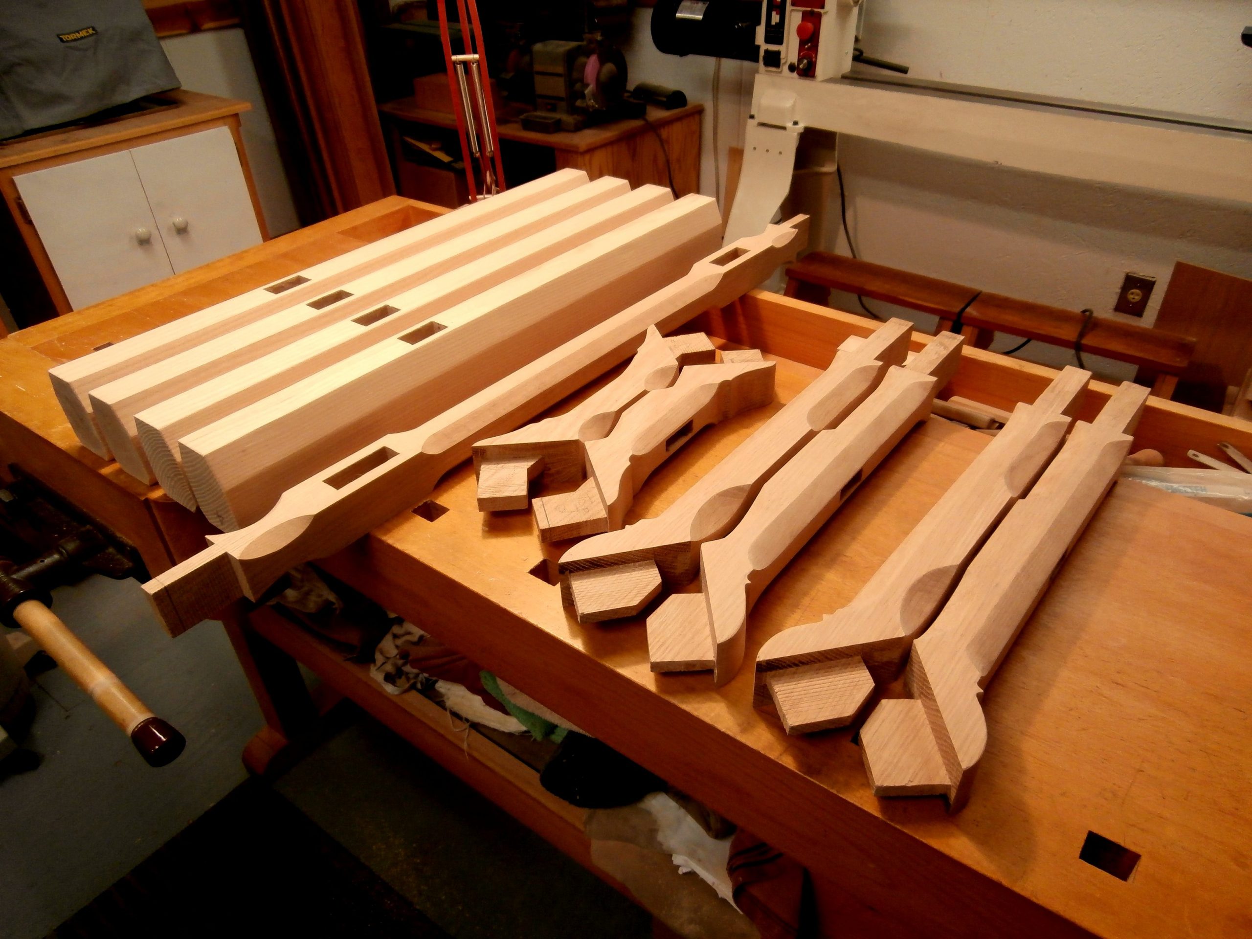
In the next stage, I used a felt tip pen to outline the reduced size of the arms with their curved detailing where the arms meet the long, center stretcher and then used the bandsaw to rough out the shapes.  Following that I used an assortment of rasps, files, planes and sandpaper to refine the curved details.  The following sequence takes you through the steps.  This was a very time consuming process, and one that cannot be duplicated with finesse by any other means.  This is what hand work is all about.

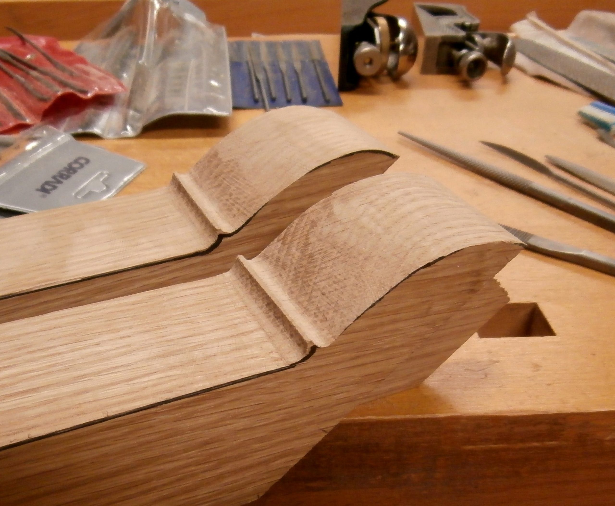
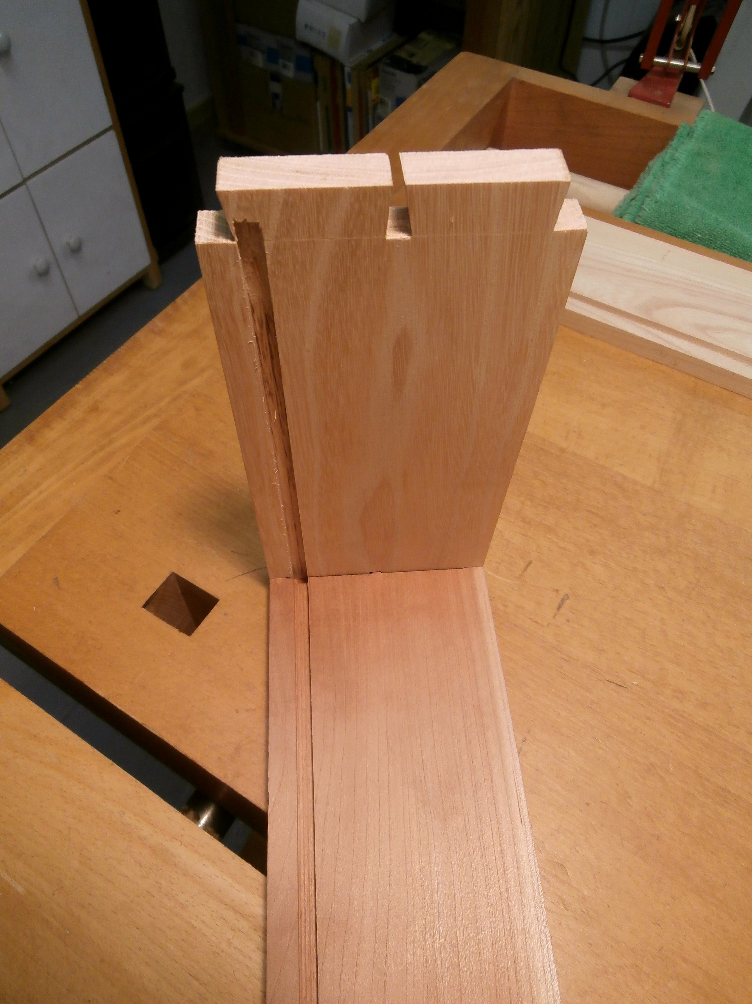
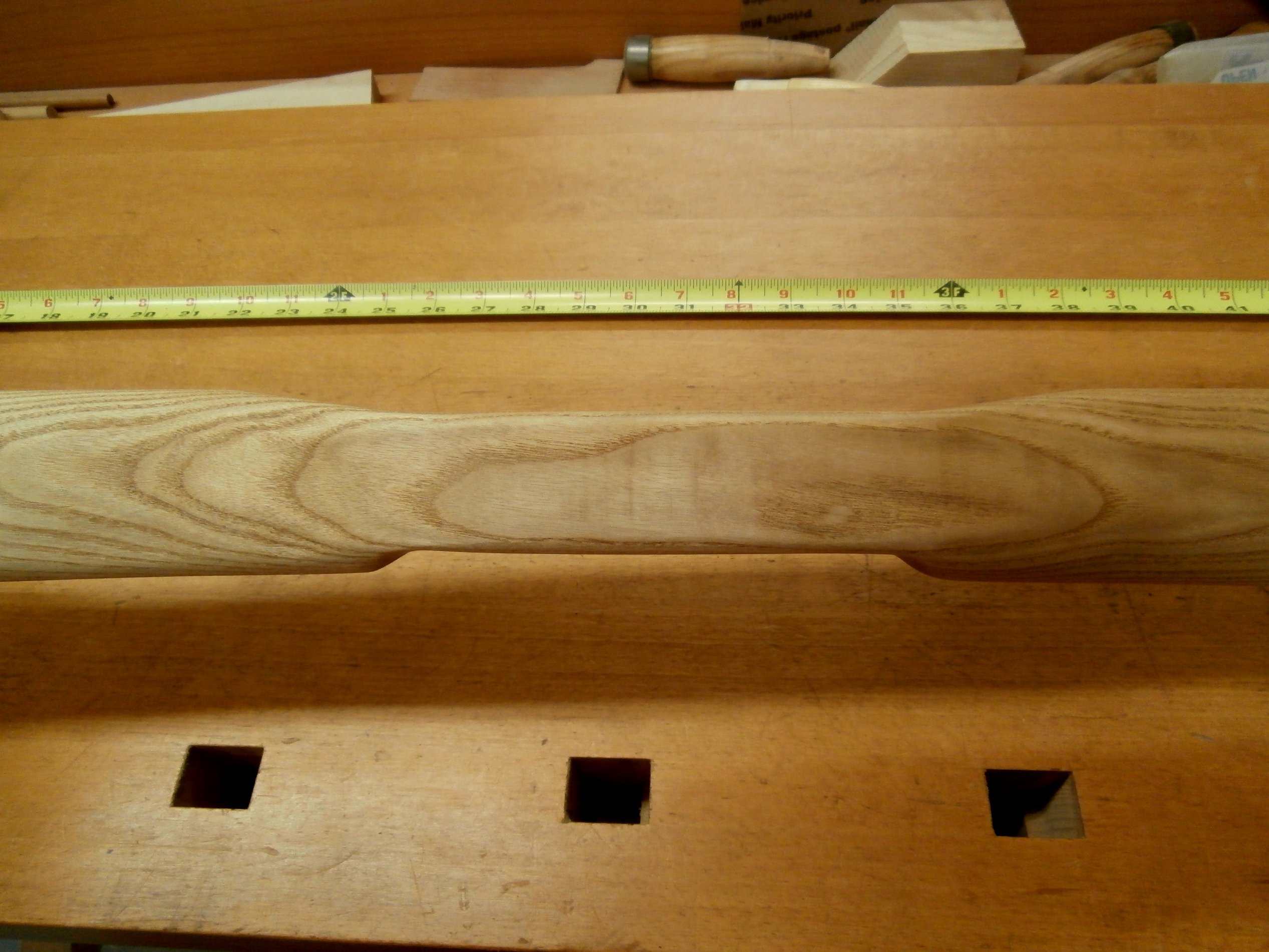
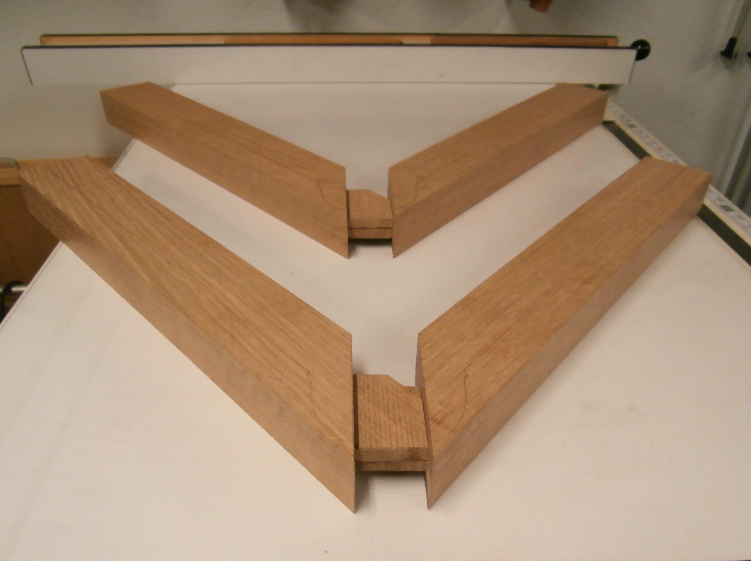
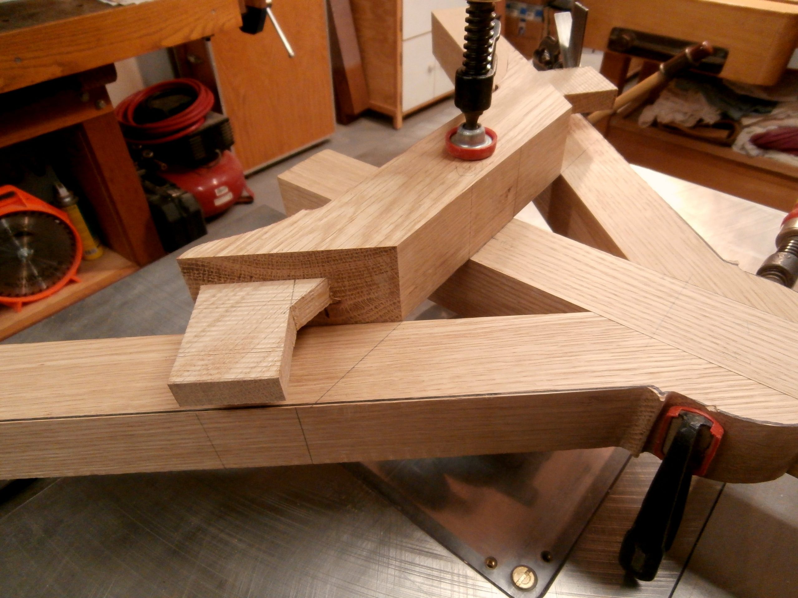
Next I dry fit the arms to the center stretcher to check my clearances.  See below.

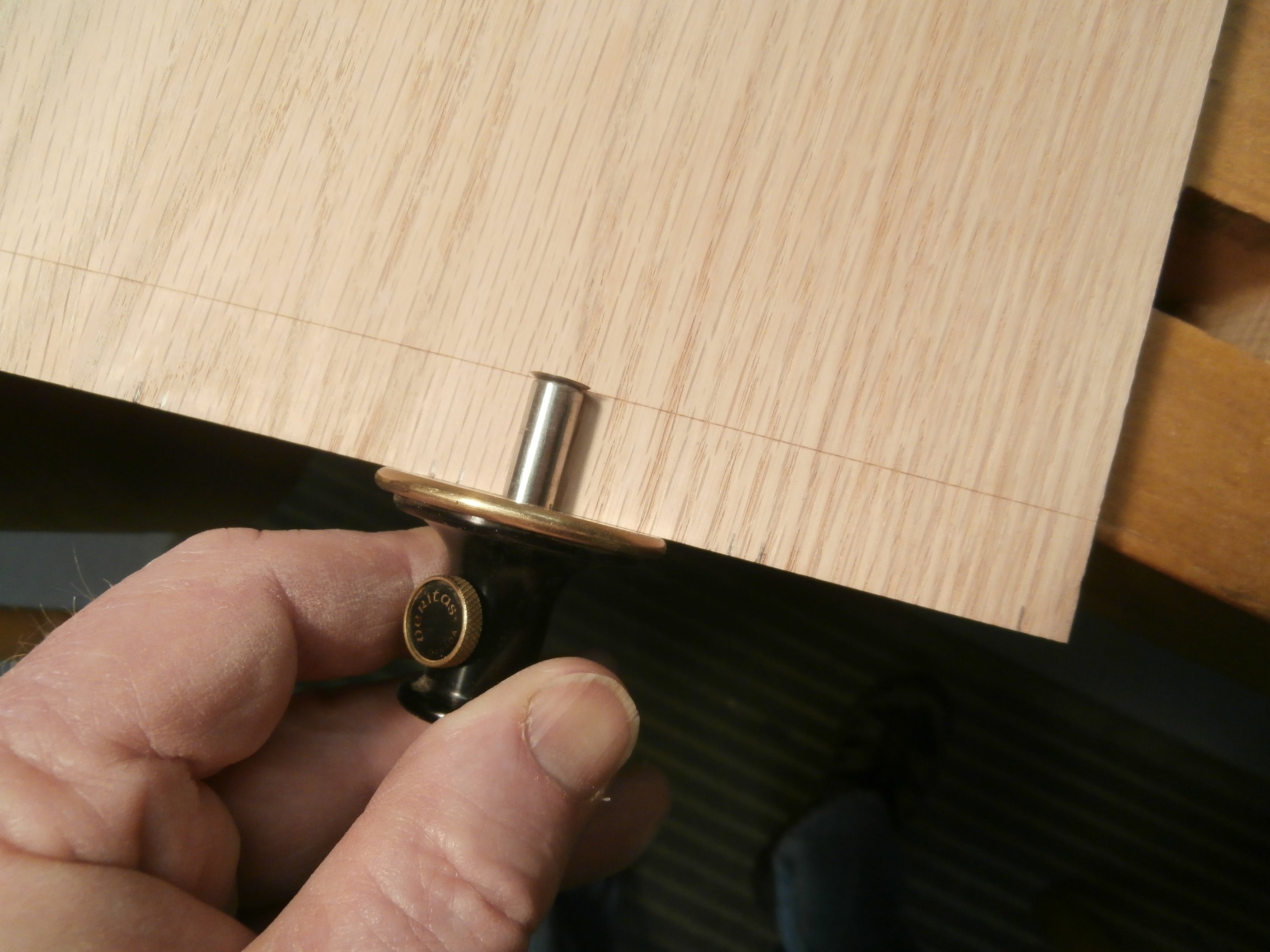
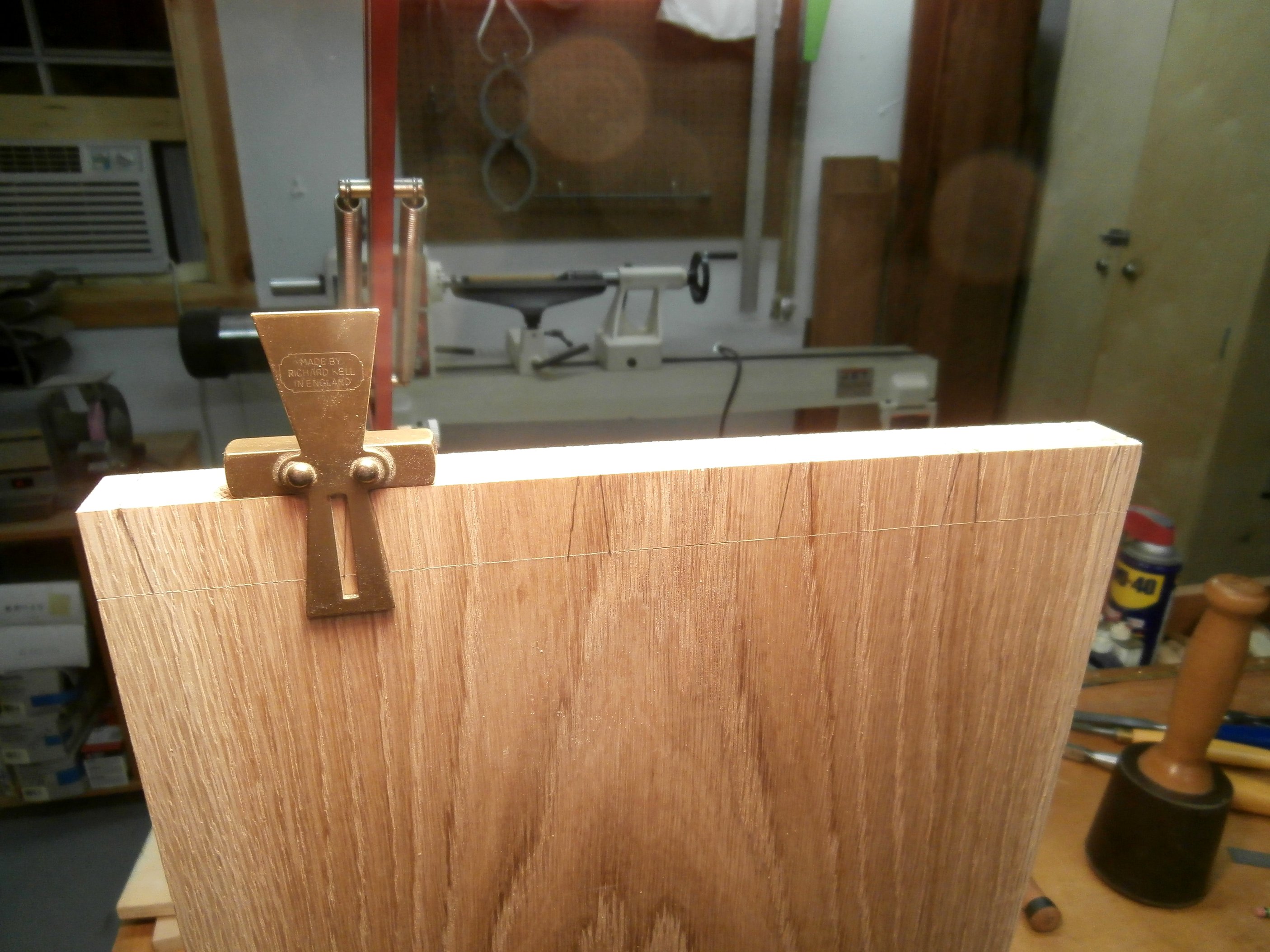
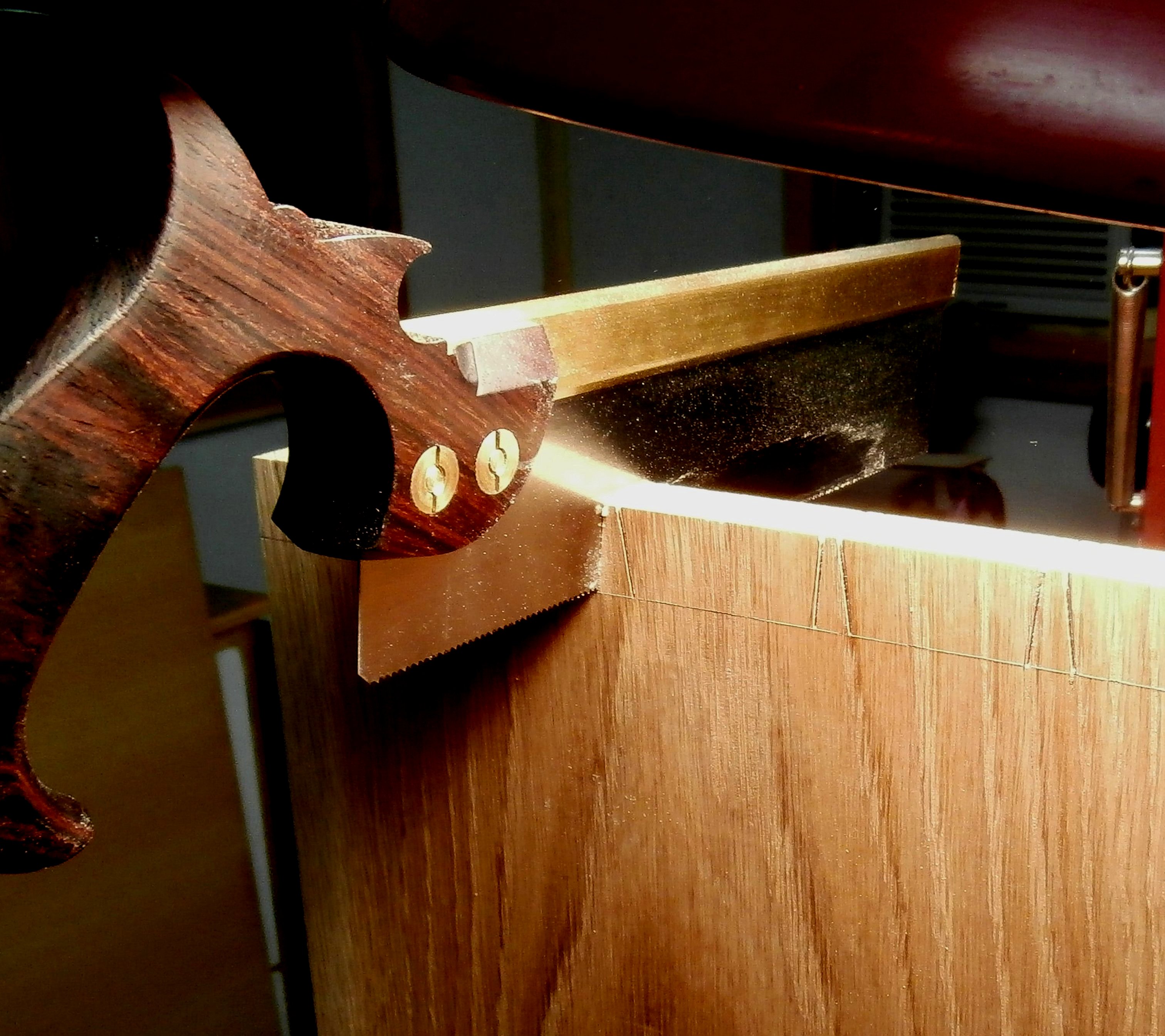
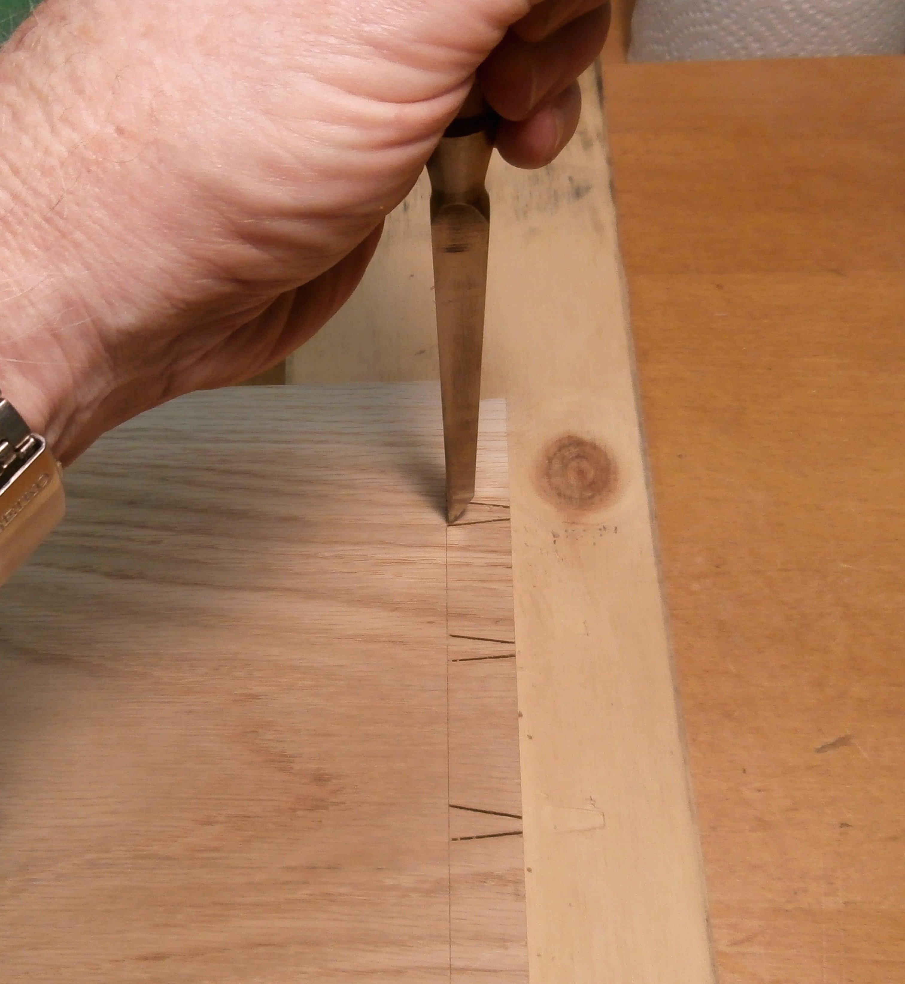
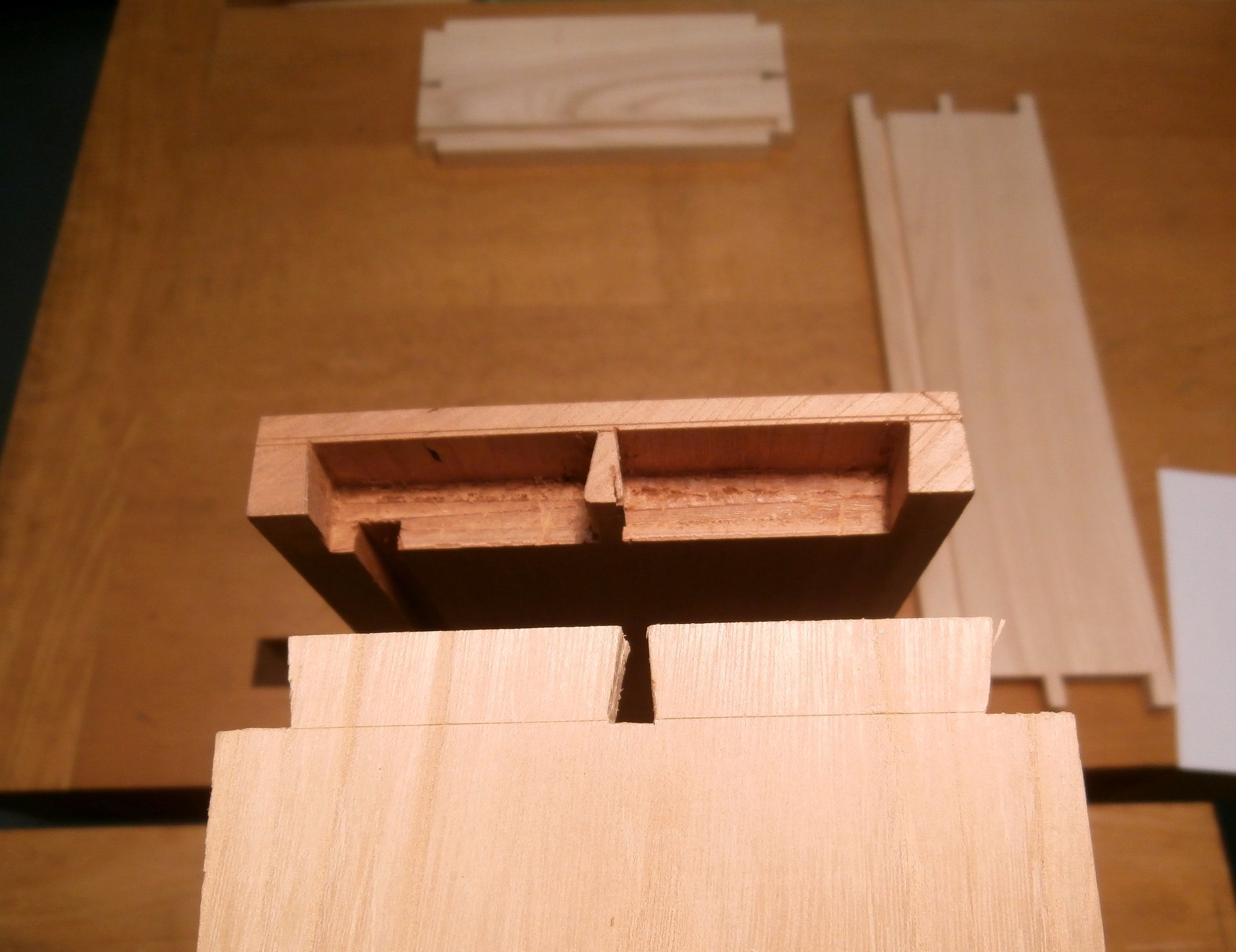
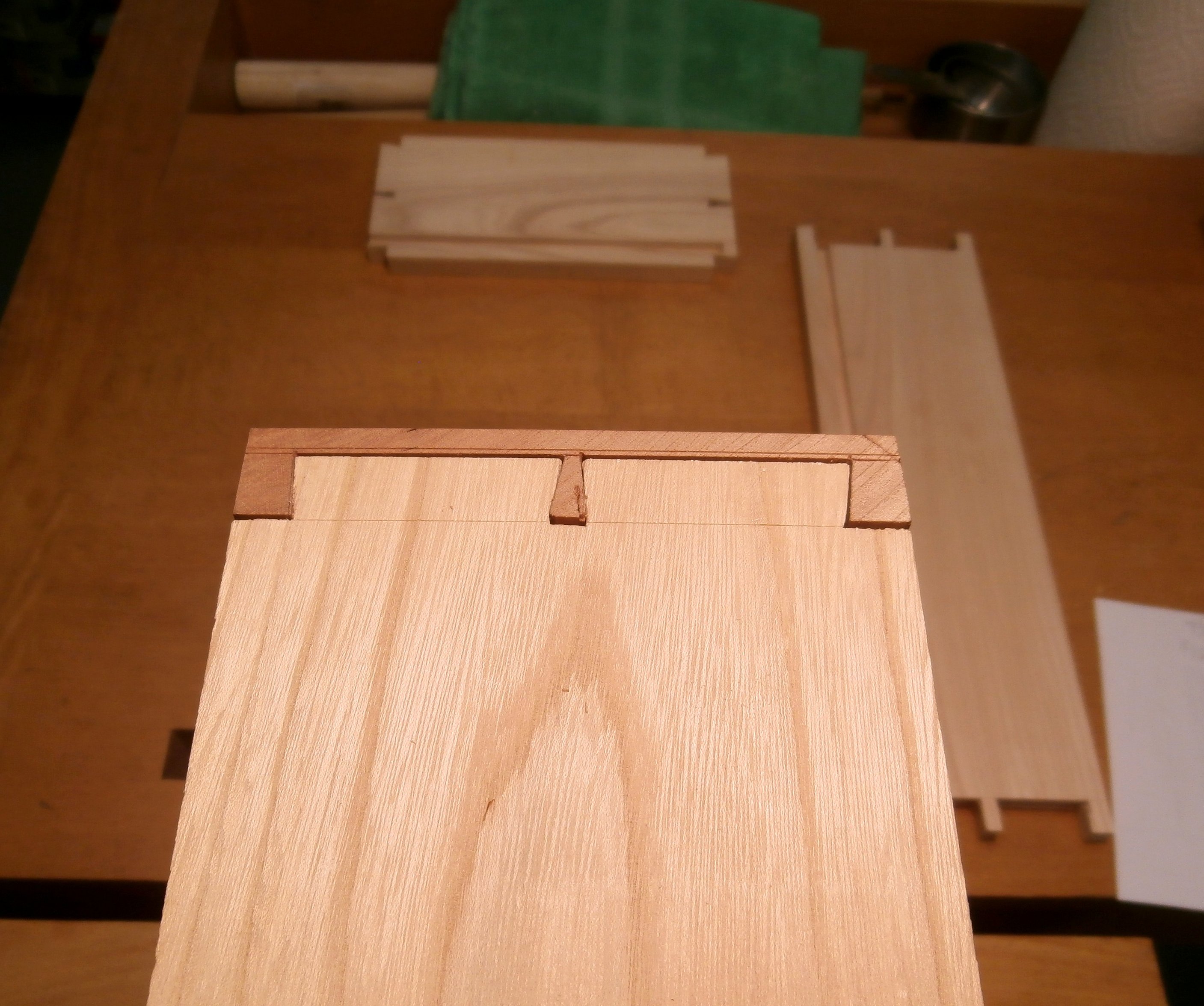
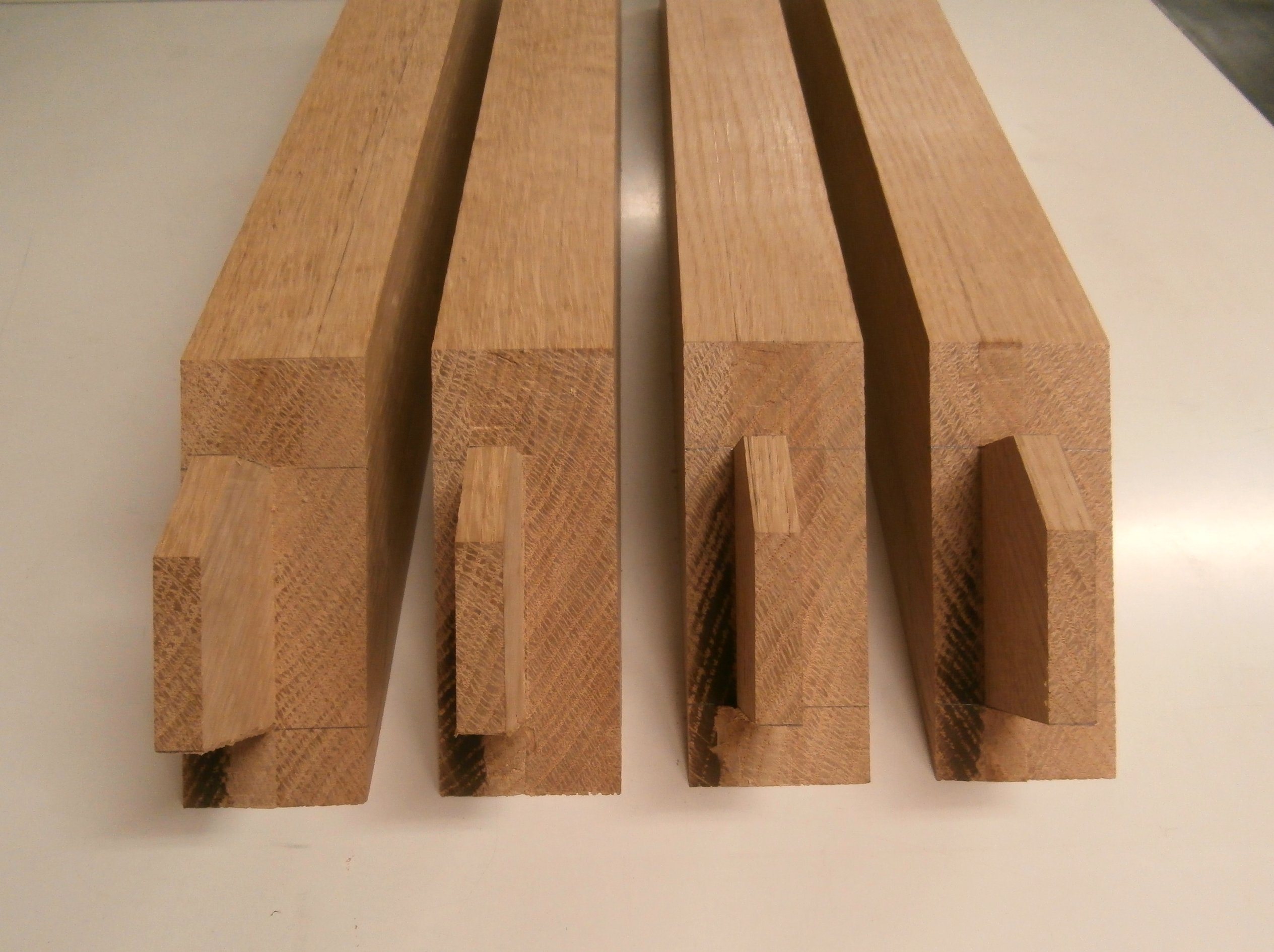
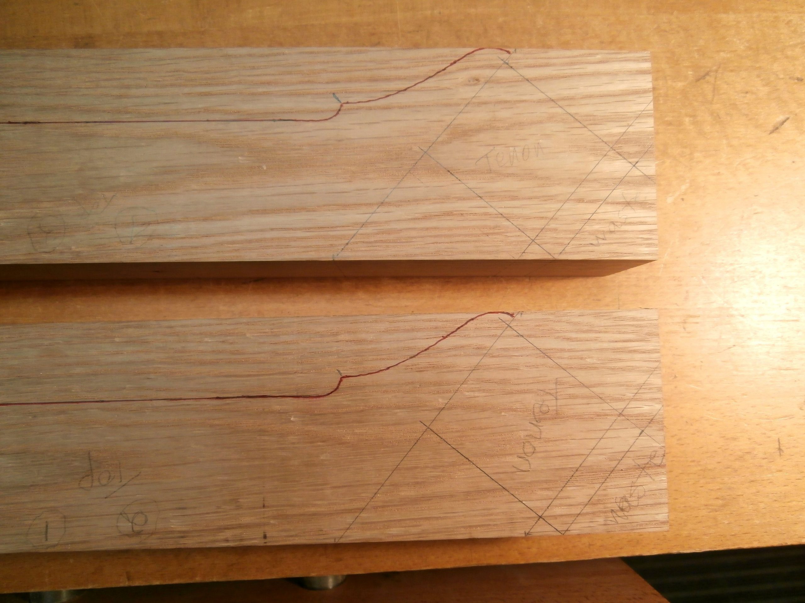
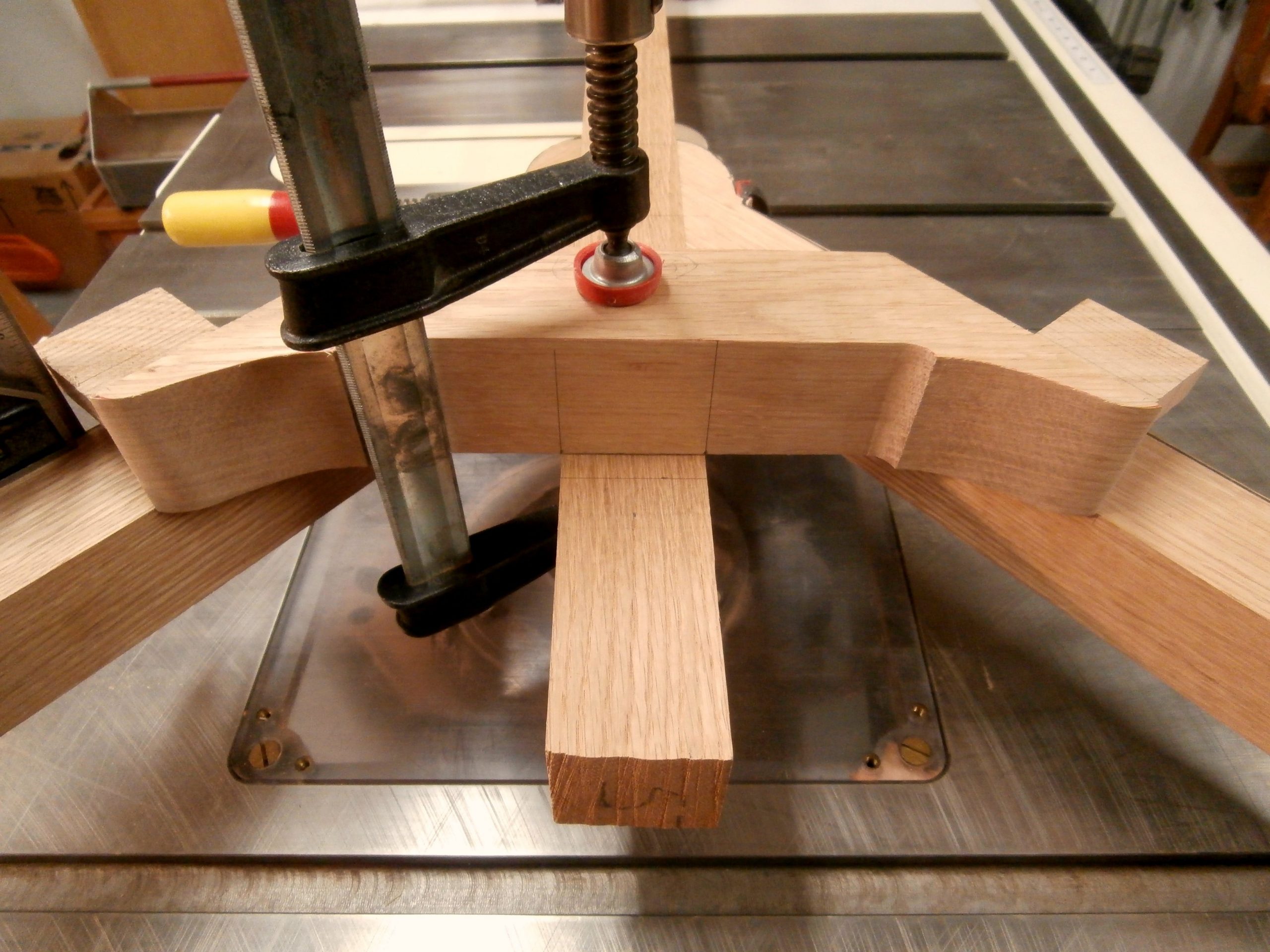
From there I consulted my full size, scaled plans for the spanner that connects the two arms and interlocks with the center stretcher.  All measurements, markings, and cuts on the spanner must be extremely precise in order for all four pieces to fit together with tight joints.  It is an added challenge  to have all the through tenons  emerge  flawlessly where they are visible on the outside faces.   Here is the sequence.

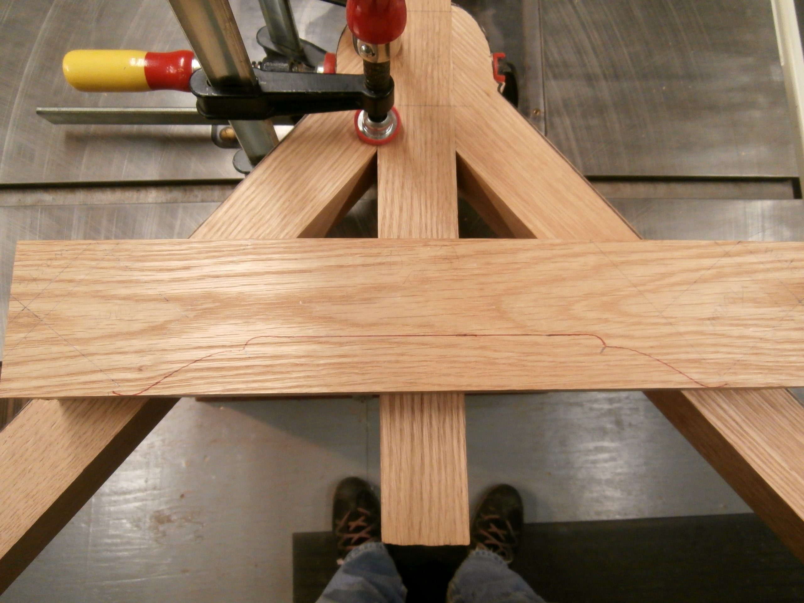
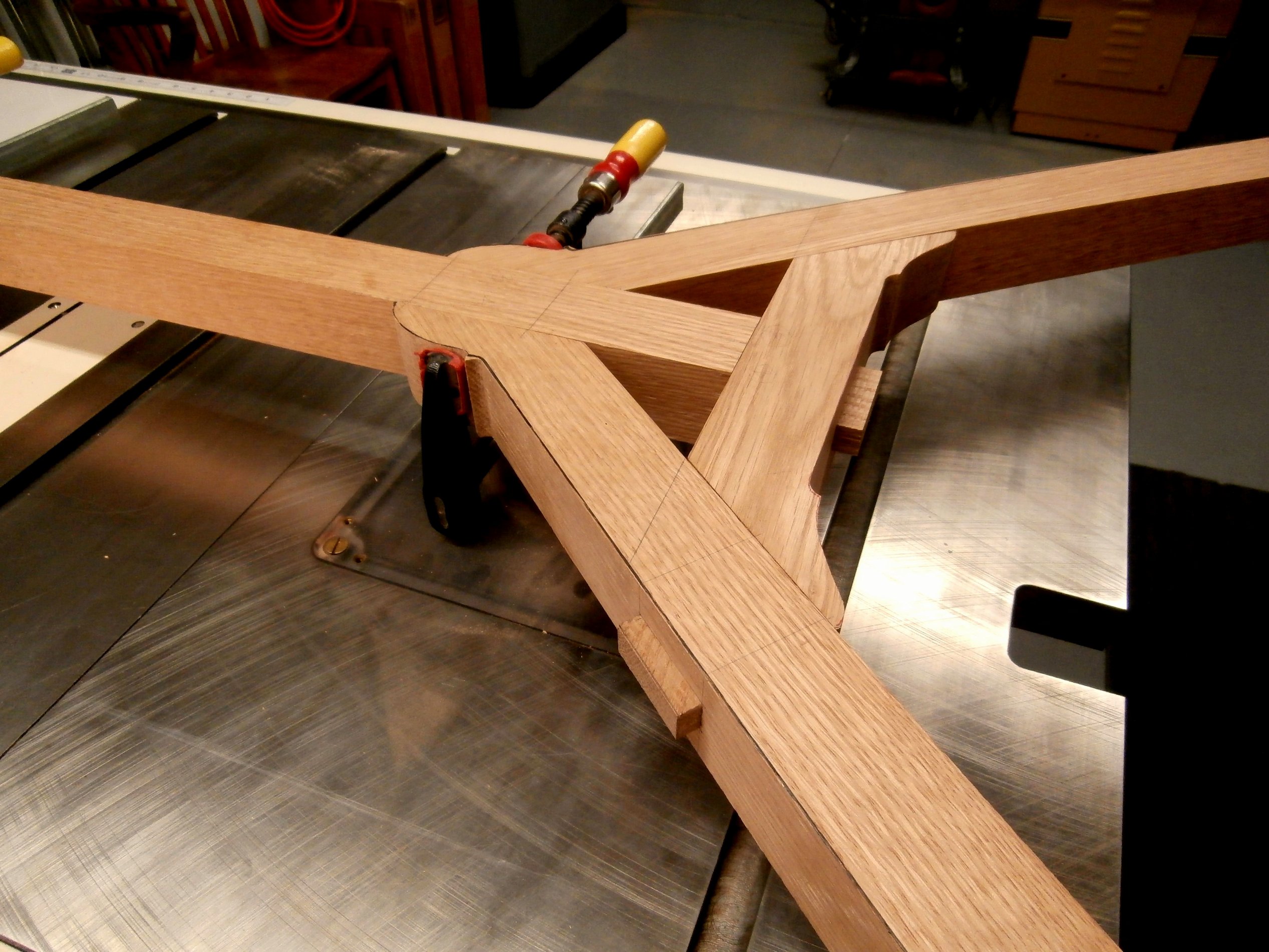
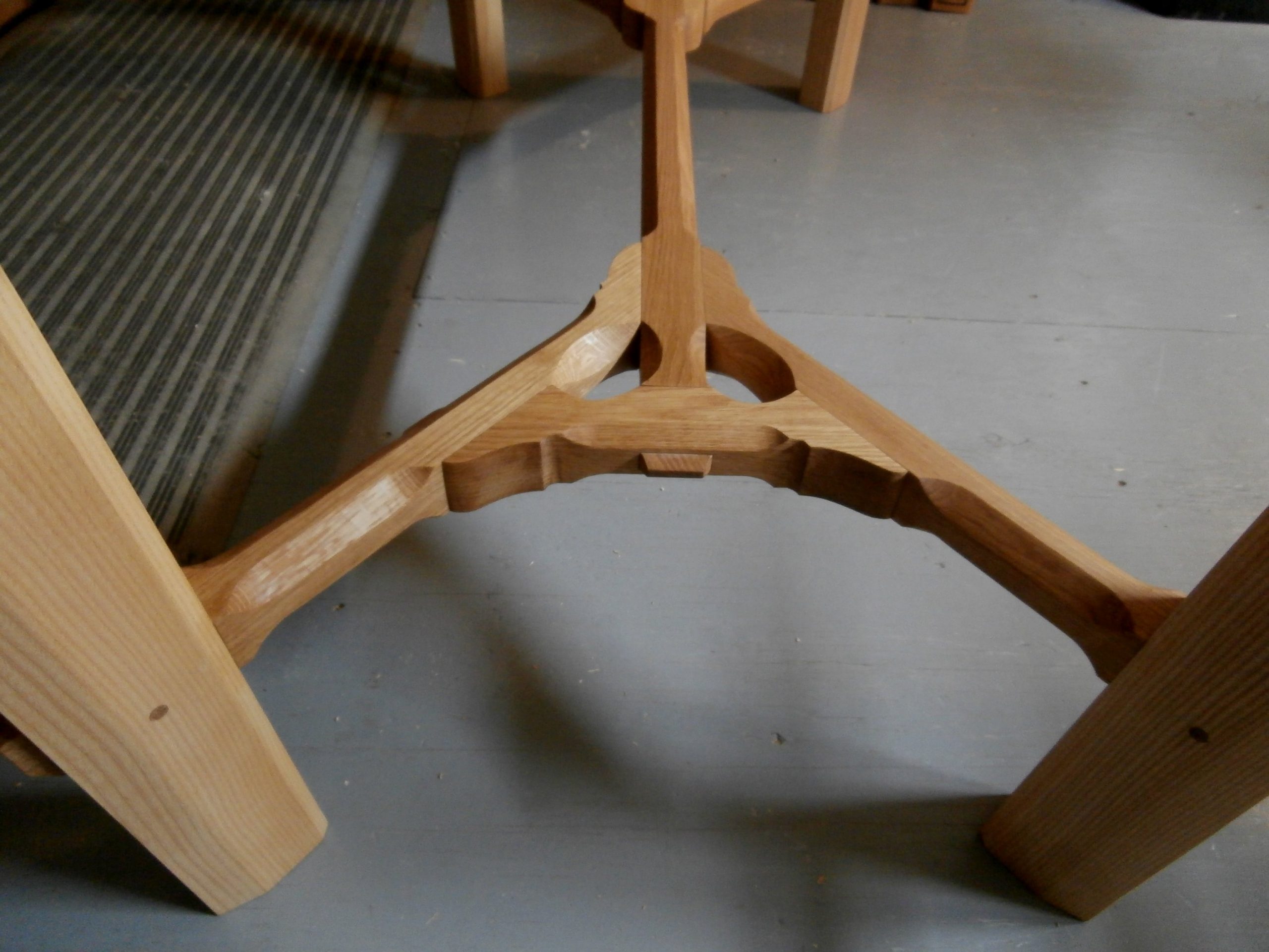
Assembled it looks like this.

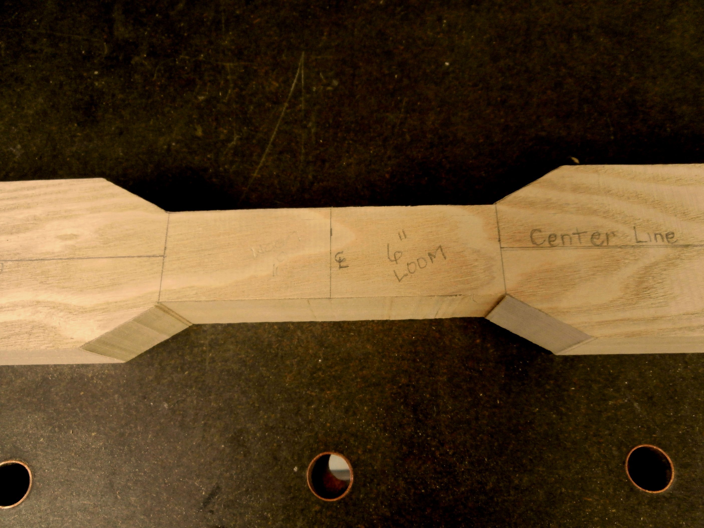
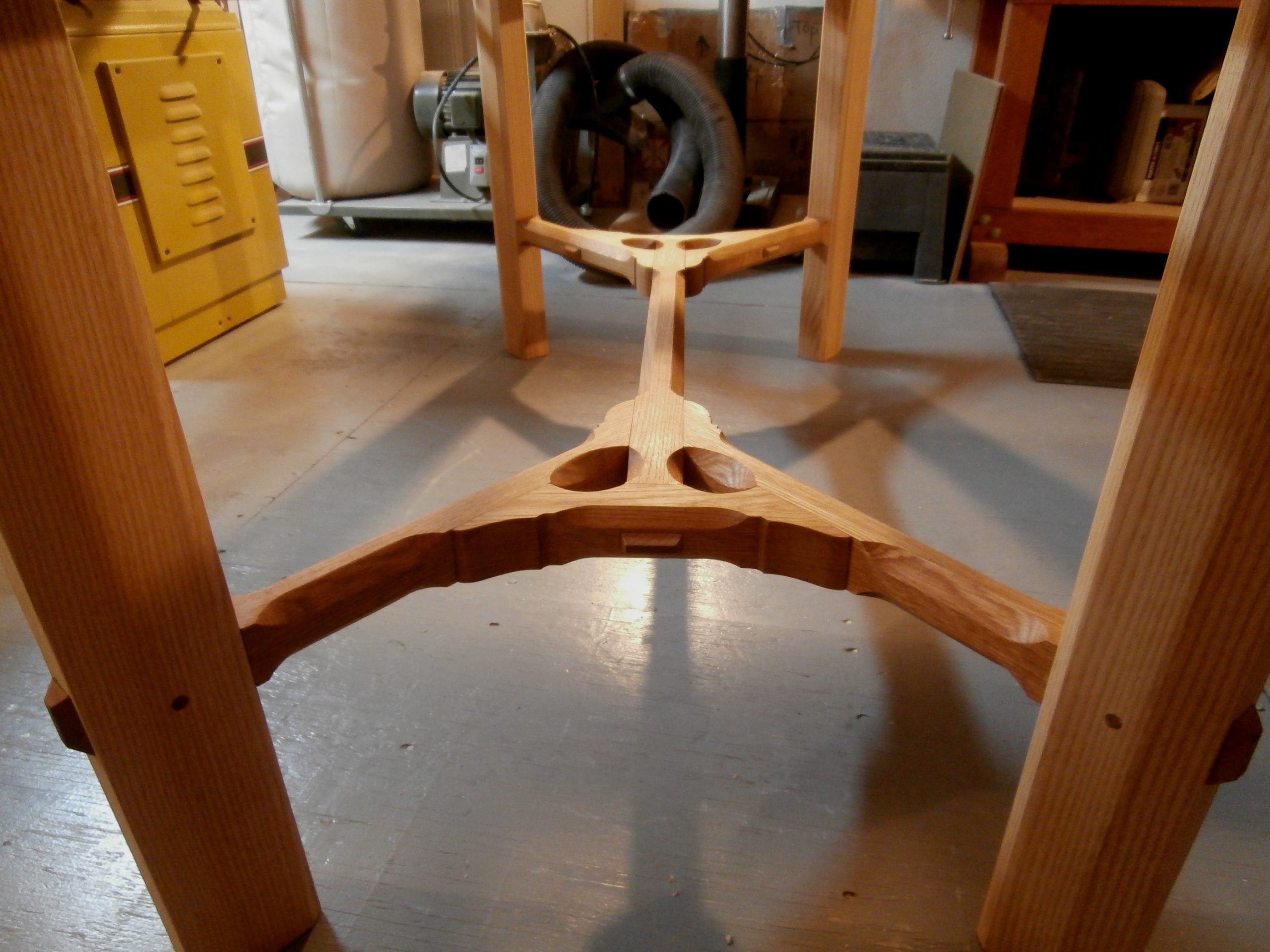
The dry fit stretcher assembly is then marked with the location of all chamfers.  The chamfers in the original hay rake do not compromise the strength of the rake, but they decrease the weight the farmer has to lift and pull for hours on end.  In the table, weight is not a concern but the chamfers add immeasurably to the aesthetic appeal of the stretcher.

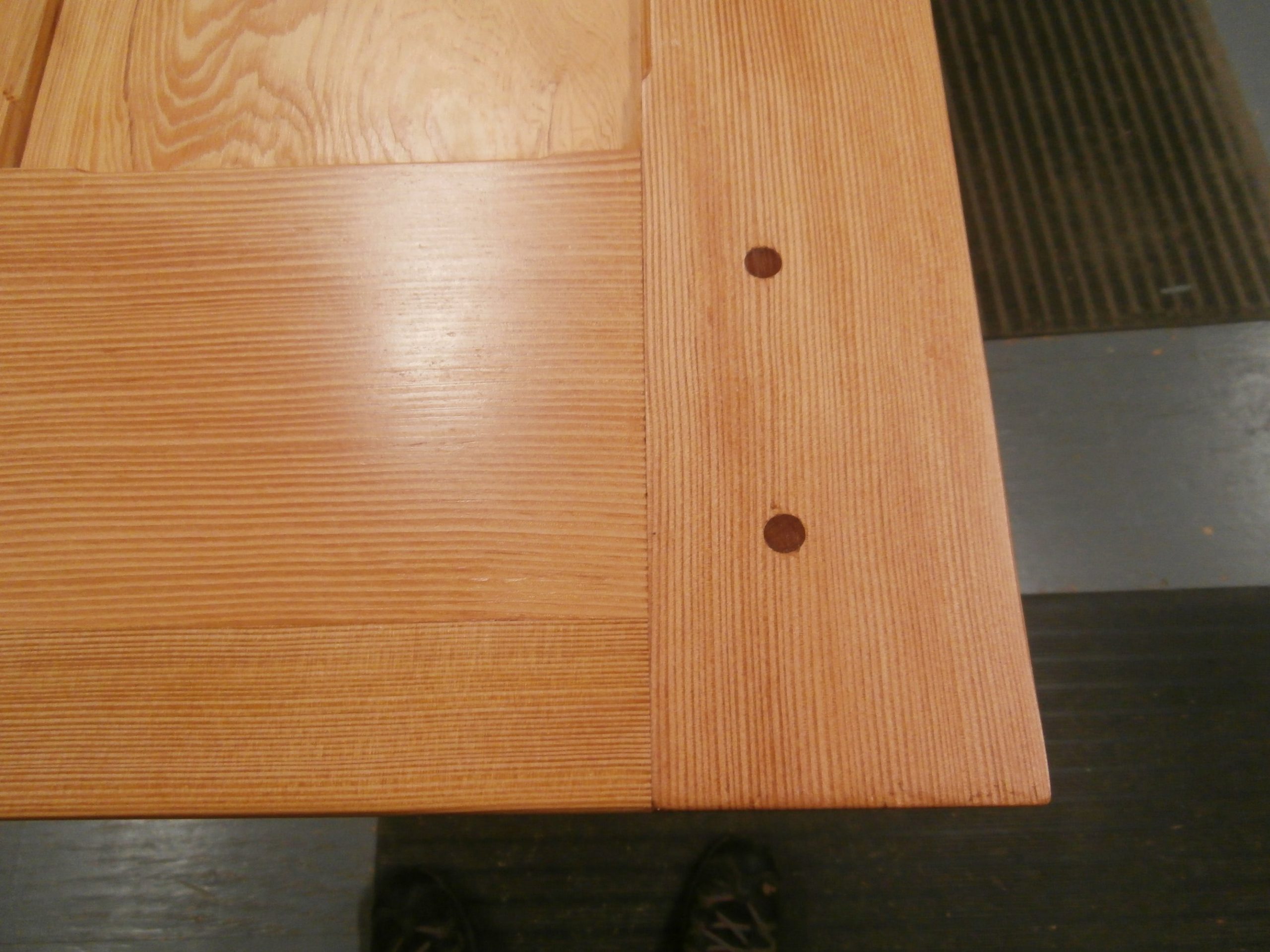
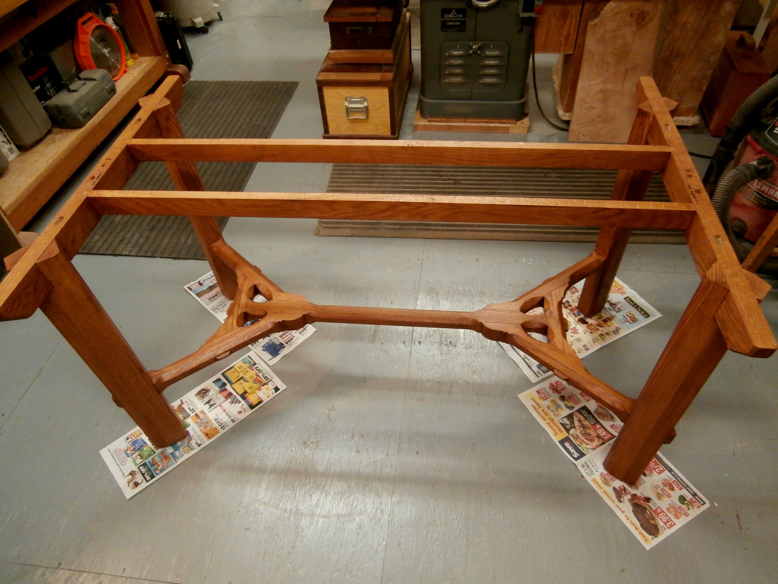
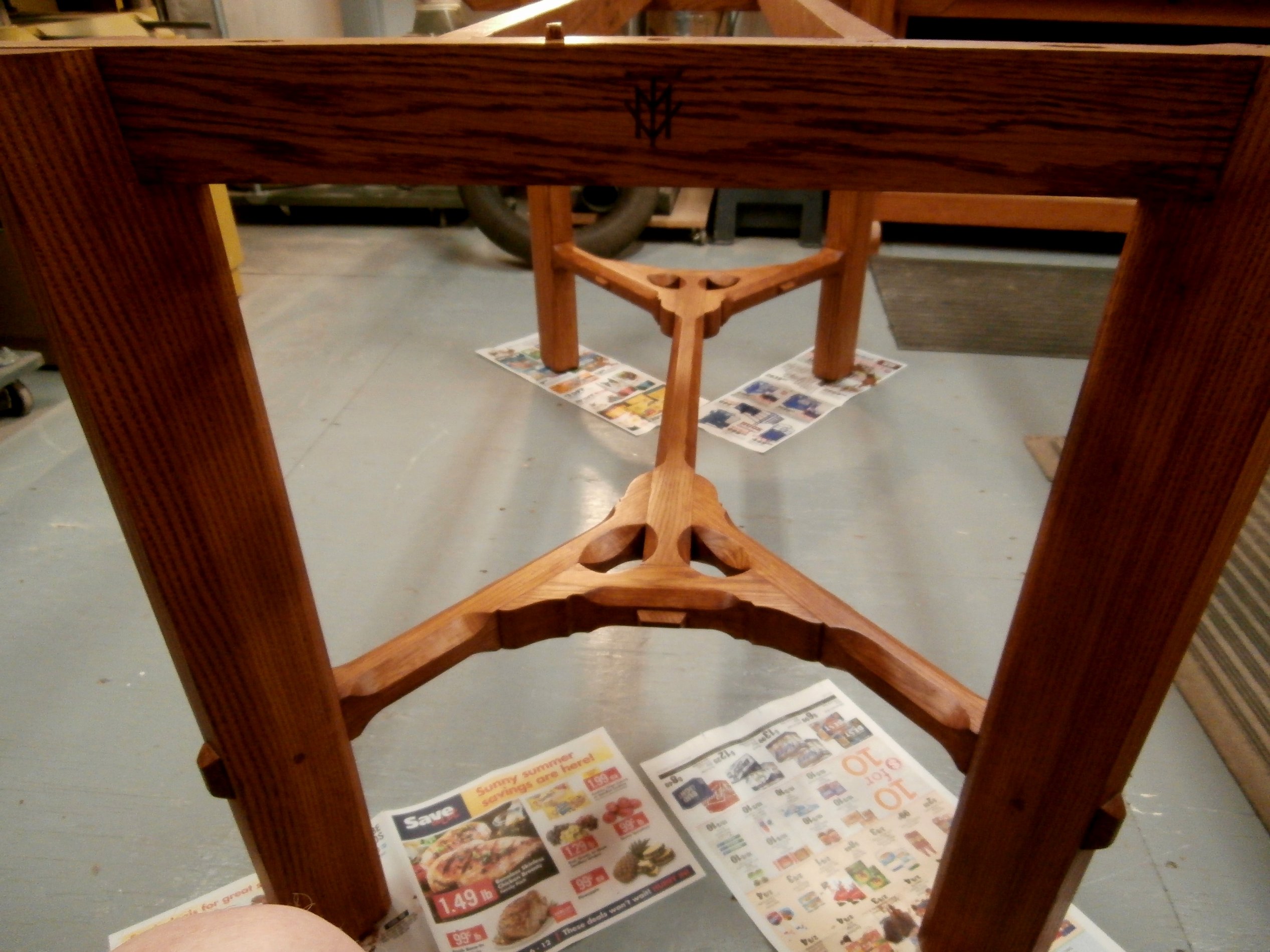
See below the full stretcher and leg set ready to go and then assembled.  Barnsley chose to have the pegs that lock the tenons in their respective mortises visible from above.  I put the pegs in from below so they do not show and therefore do not distract from the flow of the joinery.

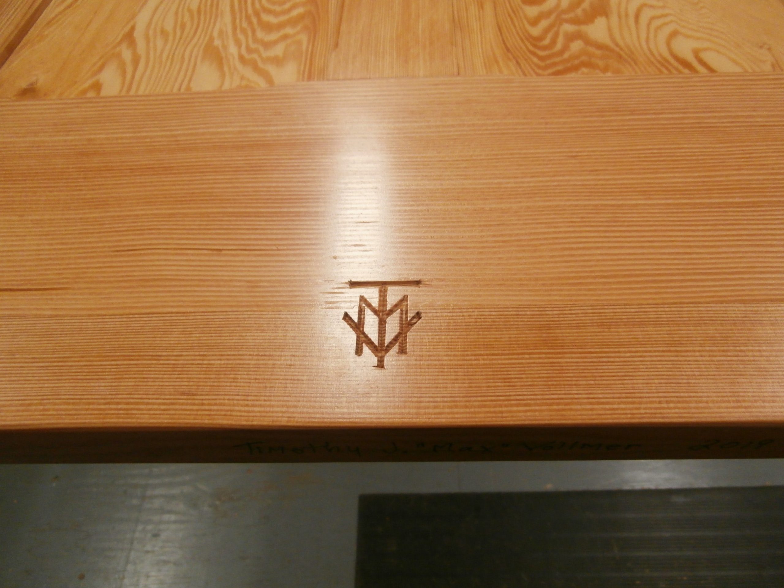
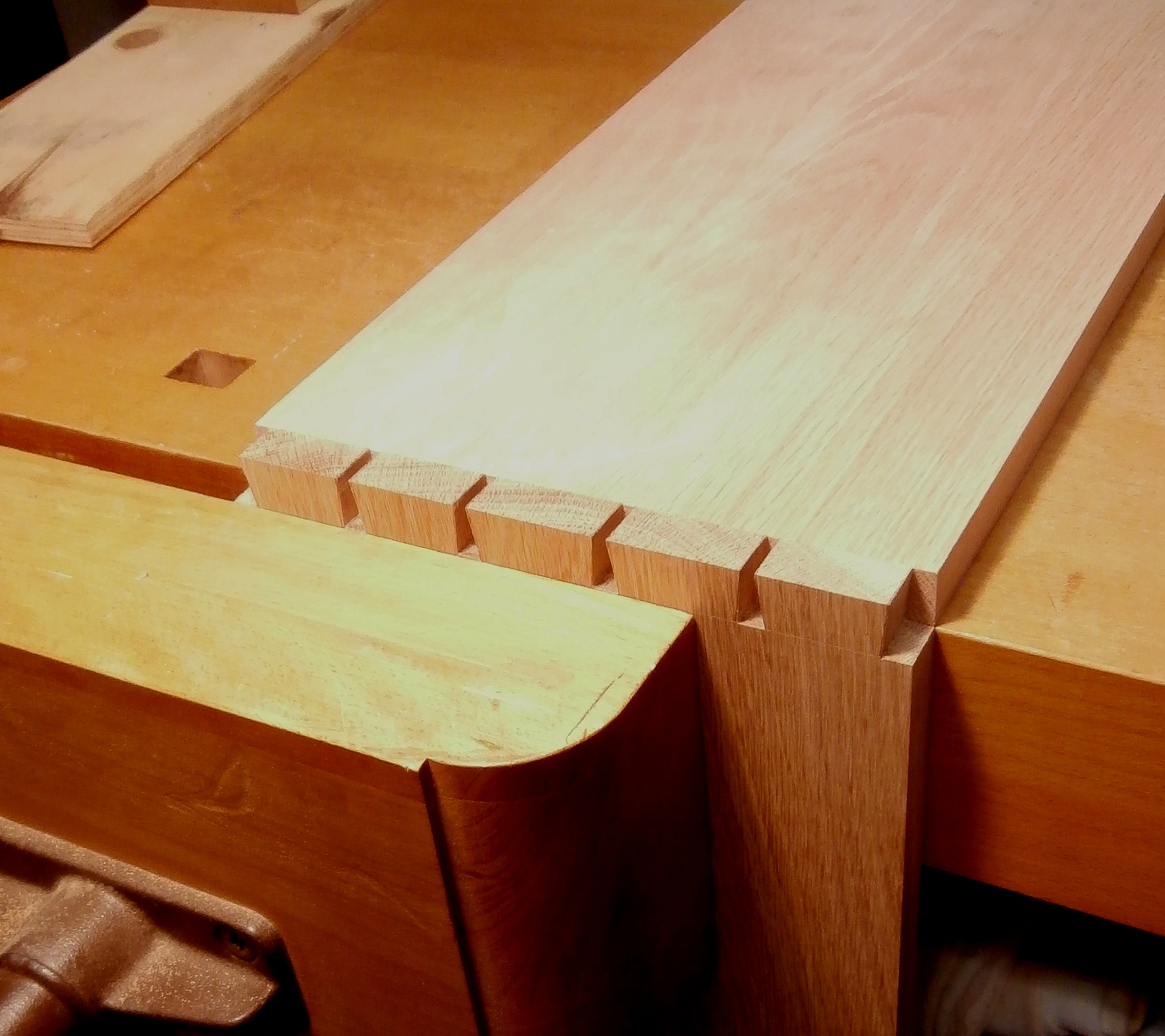
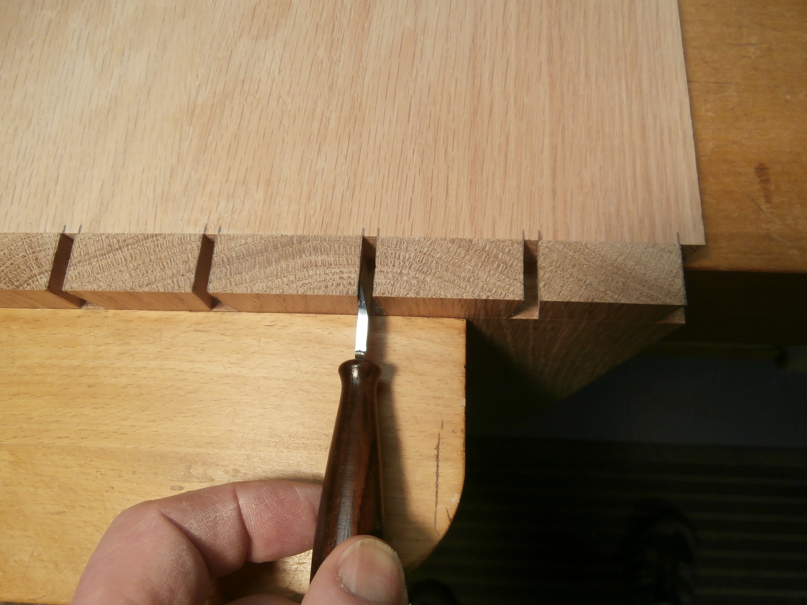
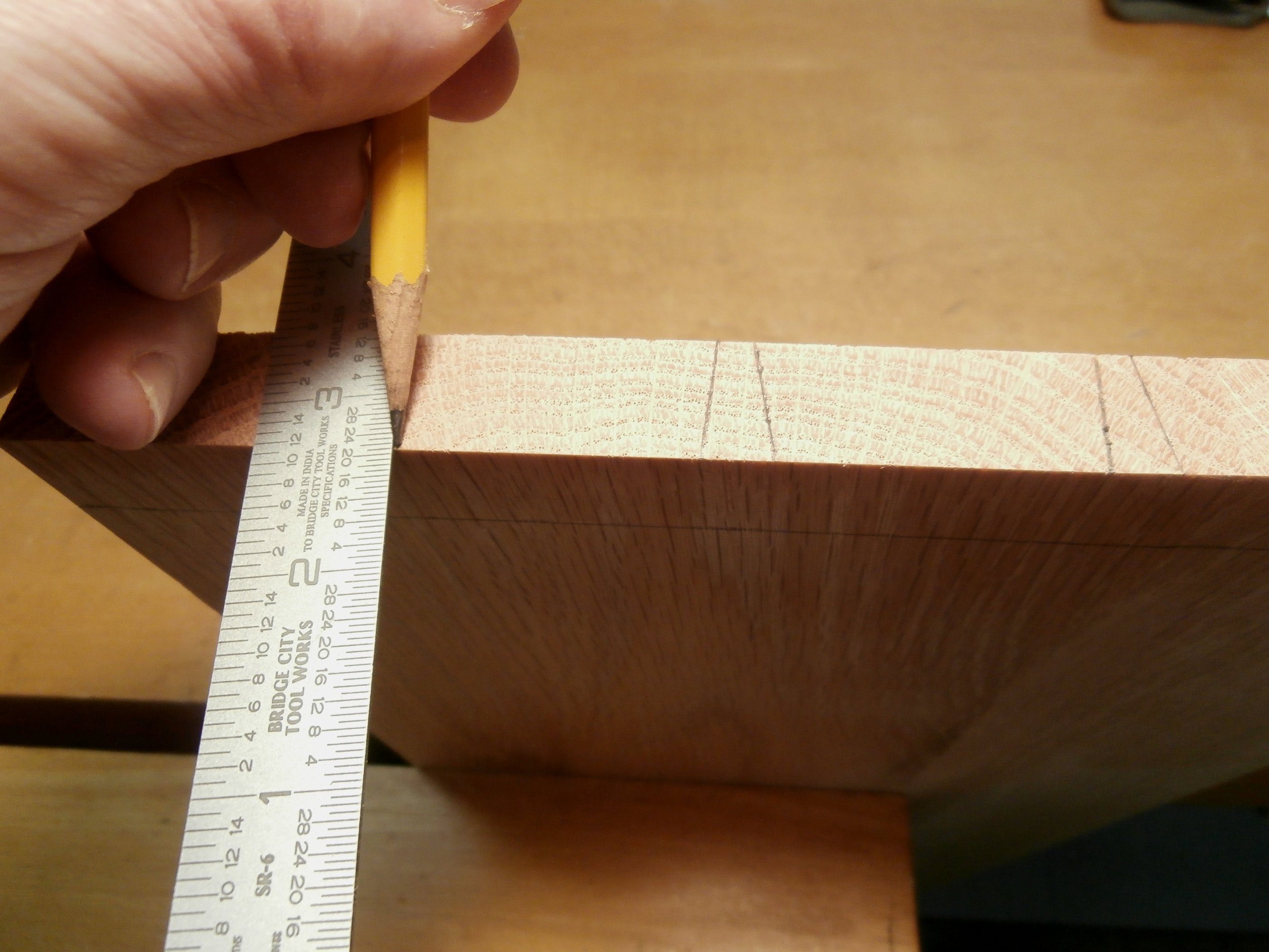
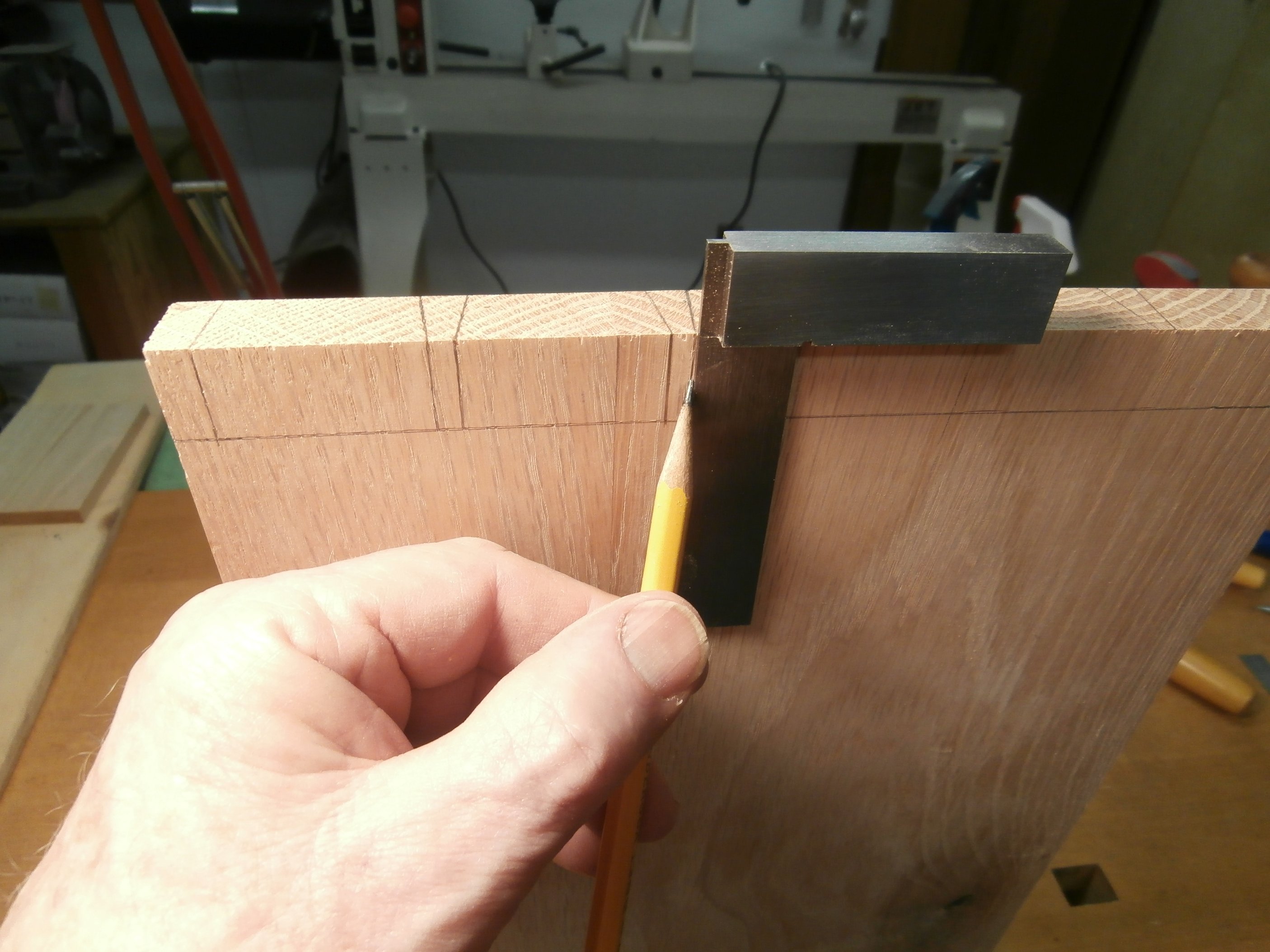
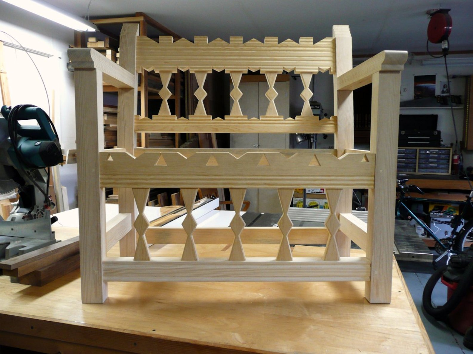
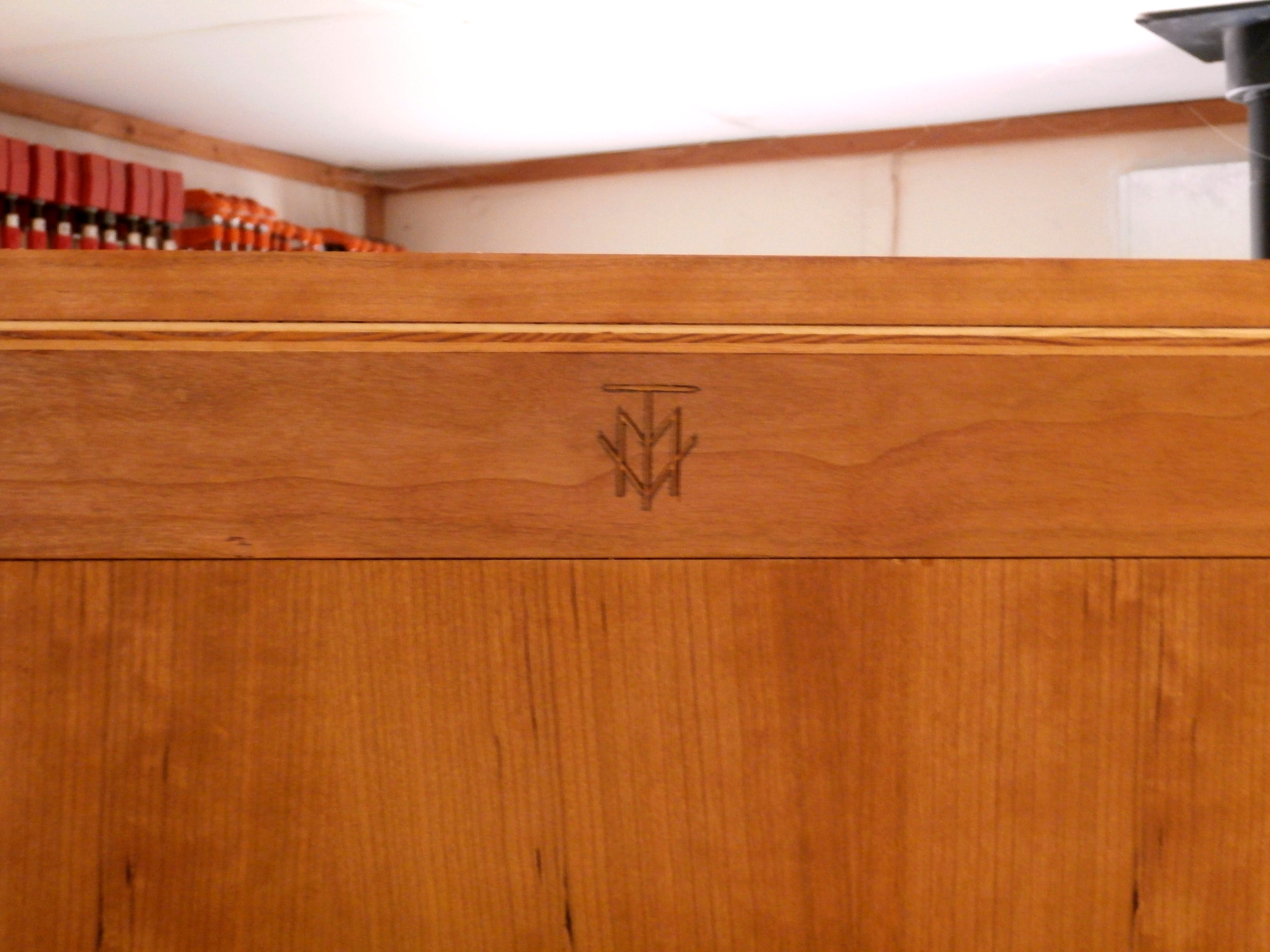
Rounding out the table frame, I fit cross pieces to the tops of the legs and then installed two long, under-table supports that are joined to the cross pieces with dovetails.  The result is a support structure that, barring fire or natural disaster, has an essentially unlimited lifespan (1,000 years?) if cared for.  Here it is with finish and signed with my makers mark on a cross bar.

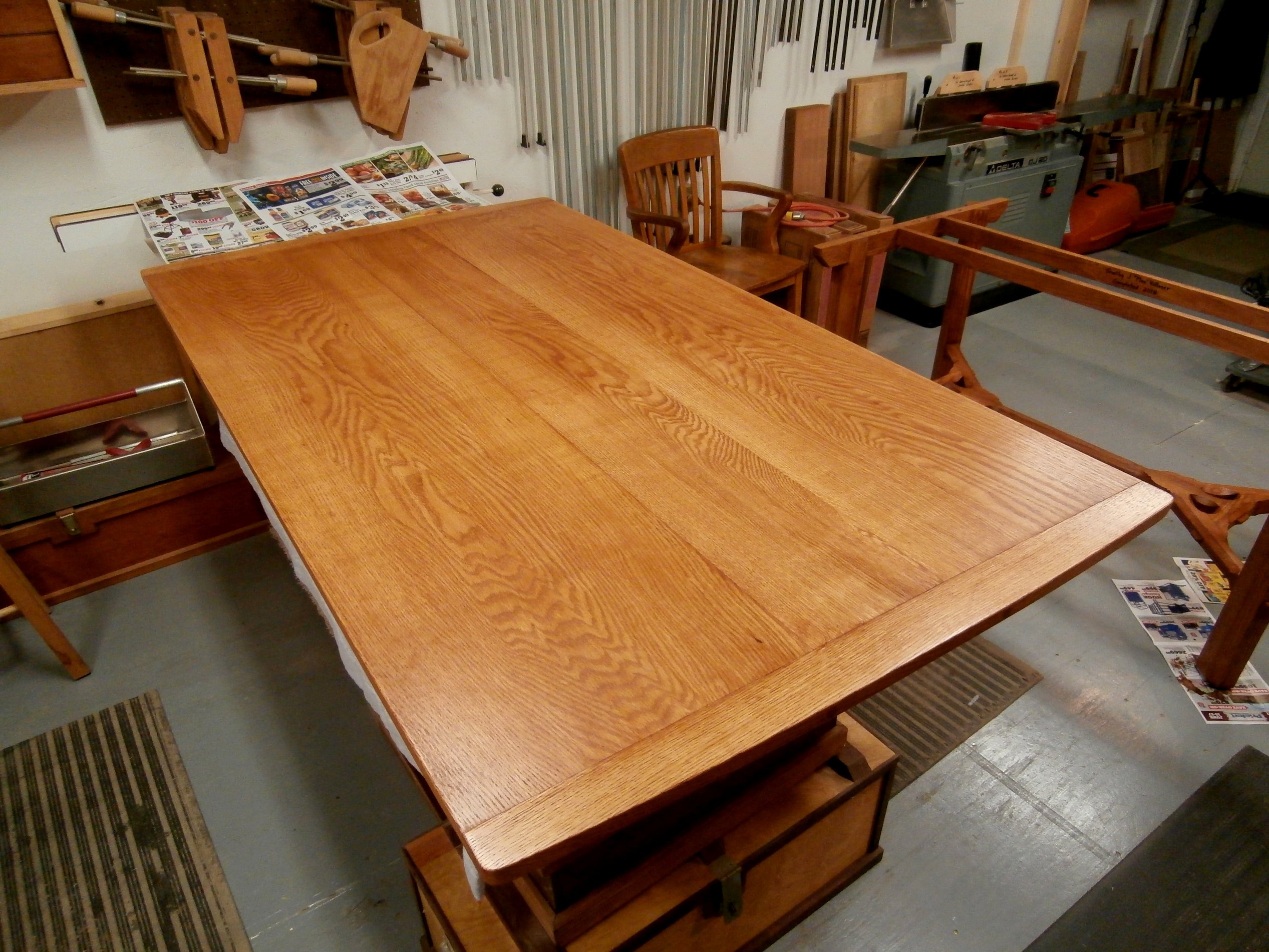
Here’s the table top.  And, following that,  the table in my house.  Final dimensions are 68″ L x 38″ W x 31.5″ H.  The table is compact, but the design of the hay rake stretcher and the canted legs allow for four chairs, across and end to end, and will accommodate four people comfortably for a meal.

I have the lumber to make a long, low, and narrow coffee table with the same hay rake stretcher design, to which I want to add wishbone struts under the table top for added complexity and interest, something Barnsley did in one of his tables.  I just need a shop.

Priest’s Chair – Palace of the Governors, Santa Fe, New Mexico

I found this picture online of an 18th century chair in the collection of the New Mexico Museum of Art in Santa Fe, New Mexico, known as the Priest’s Chair.  See below.

There are a few, early, carved armchairs like this one from northern New Mexico that are referred to as Priest’s Chairs without any documented connections to churches.  However, chairs of any kind were few and far between on the northern New Mexico frontier in the 1700’s and armchairs like this one would have been found only in the homes of prosperous Spanish families and in a few Catholic churches with larger congregations.  The wood used in the original was the best timber available at the time, Ponderosa pine from the Sangre de Cristo mountains.   I decided to make a copy of this chair, with added details, to accompany my carved New Mexico bench (October 2015 Archive) and my carved Harinero chest (January 2018 Archive).  This was the last project I completed before dismantling my shop in January 2020.

Without plans or the actual chair to go by, I based my chair dimensions on the research I did for the New Mexico bench and the old photograph.  I prepared scaled drawings and then followed my usual practice of cutting and shaping all the individual pieces for the chair, including in this case, the “through” mortise and tenon joinery used on the original (“through” referring to the fact that mortises pass all the way through the wood so that the tenon ends are exposed).  See below.  [Click on any image to enlarge, All photos copyright symbol Max Vollmer]

I then tried to estimate the original dimensions of the back splats and those in front, below the seat; drew them on paper, glued the paper down to boards, and rough cut out the shapes on the bandsaw leaving enough wood top and bottom for tenons to go into the chair rails front and back.

The front and back sub-assemblies for the chair, with carved details, looked like this.

I assembled the main chair components, leaving the armrests off at first so that I would be able to accurately locate them on the back legs of the chair.

Locating the armrests was a little tricky.  I wanted them level with the ground and at a height that would be comfortable for someone seated in the chair.  I clamped the unfinished armrests to the front and back legs, marked their position, and then marked out the mortises in the back legs.

The location of mortises and tenons were marked on the armrests and the chair legs, cut as marked, and then all that remained was to attach them.

I sealed the pine with Minwax Natural and then made a blend of Minwax tinted sealers to darken the wood.  Finally, I attached a temporary plywood seat that will be upholstered when  I get the chance.


A New Home for my Timberline desk and chair

Not long after moving to Eugene, Oregon in 1987, I traveled to Timberline Lodge on the slopes of Mt. Hood to take photographs and measurements of what are known as the Mezzanine Desk and Chair, part of the of the original 1930’s Depression era collection of furniture made by WPA (Works Progress Administration) artisans for the lodge.  I did that so I could make an exact reproduction of the two pieces.  Below you see a picture of the cover of a book on Timberline Lodge published by Friends of Timberline in 1978 and a photograph from the book of the original desk and chair in one of the alcoves on the lodge’s mezzanine level.

My reproduction differed from the originals in two repects:  one, I used clear vertical grain (CVG) Douglas fir while the originals are made of Douglas fir with knots; and two, I made rubbings of the carved five-petal flower on either side of the upper portion of the desk in order to replicate the carvings on my reproduction.

With no plans to guide me on the actual construction of the heavy-timbered  desk and chair, I settled on what I thought would be the most durable way to secure the leg and stretcher sets for both, and that is through the use of sliding dovetails.  Although I do not believe this is the technique used on the originals, it made the greatest sense to me because of the fact that both leg sets are splayed outward creating compound angles where the legs connect to the skirts and the stretchers, as you can see in the photograph above.  The desk legs were approximately 4″ x 4″ square and the chair legs were approximately 3.5″ x 3.5″ square.   Constructing the legs sets so that the splay angles matched those I had measured in the originals was a  challenge, involving the use of the traditional sliding T-bevel.  Below you can see the leg set for the chair, and the skirt sets for both the desk and chair, prepared for assembly with the dovetail slots and keys.

In the next two photos you can see a detail of how the skirt pieces are joined to a leg, and then the fully assembled leg set for the desk.

The rounded profiles on all four legs of the desk and chair were created prior to assembly by rough cutting the profile one leg at a time on the bandsaw and then finishing by hand with wood rasps, files, and what are called wood “floats,” and finally sandpaper.

The pieces for the desk top, the seat and back for the chair, and the upper section of the desk were all worked with handplanes to create the smoothest surfaces, smoother by far than what is possible with  sandpaper.   Below you can see my use of a jack plane to refine the edge of the desk top.

The next photo set depicts the desk and chair assembled, with a detail of the chair back support, but prior to the application of any finish.

With a Minwax Natural sealer and a Watco Danish Oil natural finish, the set looked like this when new in 1987.

I used the desk and chair from 1987 until 2020 when I sold the two pieces and the 1978 Friends of Timberline book to a couple in Portland, OR.  The wife in particular has a love of Timberline Lodge and has collected Timberline memorabilia, including commemorative Timberline Lodge blankets woven by the Pendleton woolen mills in Pendleton, OR, to display in one corner of her home.  The couple have two children who use the desk now for homework.  I could not have asked for a better home for my work.  Here are two pictures she sent me of the desk and chair in their new home.

Emily’s Pocket Door

My daughter and her partner are building a Tiny House from the ground up in Nehalem, Oregon.  My contribution is a pocket door for the bathroom.  For this project I selected some  rough sawn, old-growth, clear vertical grain (CVG) Douglas fir that I had been hoarding for 30 years for the door frame and panels.  [Click on any image to enlarge, All photos copyright symbol Max Vollmer]

CVG Douglas fir beams and boards.

The first step was to size and plane the lumber according to my plan and cut list for a six-panel door with a stained glass mosaic visible from one side only.  Then I cut the mortises and tenons for the door frame and dry-fit the pieces.  It is absolutely critical for a door that the frame be dead-square, with 90 degree angles at all joints.

Checking for square.
Door frame, dry fit.

The next step was to cut the rabbets all around the inside of the frame members to accept the 3/4 inch thick panels.  As with any frame and panel construction, allowance has to be made for the expansion-contraction of solid wood panels that occurs with changes in ambient humidity.

Dry-fitting panels in the rabbets cut into the door frame members.

With the door frame members sized, the mortises and tenons cut, and the panels sized, I now had a door “kit” ready for embellishment, sanding, and assembly.

The pocket door “kit.”

To add a little interest, I created 45 degree, stop-chamfers around all framed openings in the door on both sides.

Stopped-chamfers.

The side of the door that faces out was planned with a stained glass mosaic depicting a cormorant perched on a piling in the surf, a common sight on the Oregon coast.  The hand crafted mosaic was glued down to a 1/4 inch thick masonite panel sized to fit the door frame.

Stained glass mosaic.

My plan called for the stained glass mosaic to be recessed 1/4 inch in from the front surface of the door frame and “picture-framed” with thin, beveled pieces of fir.  Then backing up the mosaic, and on the back side of the door, I cut and planed thin but solid fir panels to make it appear as a six-panel wood door on the reverse side.

Front side with mosaic.
Back side.

Because this is a pocket door and will slide into a cavity in the wall rather than be hung from hinges, I used door pulls that were inset flush with the door surface, instead of regular door knob hardware.  To retrieve the door from the pocket when it is open, I used an edge pull inset into the door frame.  Finally, we wanted to employ a rare-earth magnet catch to hold the door closed and you can see one-half of that magnetic catch installed above the edge pull.

Recessed door pull.
Edge pull and rare-earth magnet catch.

Although the framing members were glued at the mortise and tenon joints, I built in extra stability and longevity by pinning the four corners of the frame with 1/2 inch cherry dowels that are visible only from the back side of the door.

1/2 inch cherry dowels pin all four corners of the door.

I signed the door on the bottom edge of the back side with my “makers mark.”

The “makers mark.”

Here are photos of the finished door, front and back, in my shop.

Front.
Framed mosaic.
Back.

Wall Cabinet – Oak, Cherry, Elm and Maple

I made this small, wall mounted cabinet to hold my layout tools for measuring and marking.  It puts them within easy reach and keeps them organized.  I used some off-cuts of red oak, black cherry, American elm, and sugar maple that were too good to throw away.  And I used some of the same tools that are now housed in the cabinet to make it.  [All photos copyright symbol Max Vollmer, Click on any photo to enlarge]

Wall cabinet. [Click on any photo to enlarge]
I’m going to illustrate the step-by-step process I use for hand cut dovetails, both the through dovetails on the case and the half-blind dovetails on the drawers.

Step one:  having determined the dimensions for the cabinet and cut the component pieces to size, I started the through dovetails for the case by marking the length for the tails based on the thickness of the board to which they will be joined, using an adjustable marking gauge made by Veritas Tools in Canada.

Marking the length of the tails.

Having decided on my dovetail spacing, I then marked the tails with a brass dovetail guide made by an Englishman, Richard Kell, many years ago.

Marking the tails.

The next two steps were to cut alongside the marked tails and then chop out the waste between them.

Using a chisel to chop out the waste between the dovetails.

To align the dovetails with matching pins, I clamped the board with the finished tails in my bench vise and lined up the board that will have pins and marked their location.  With the spacing marked in pencil, I used a marking knife to inscribe the outlines of the waste between pins.  I go to all this trouble to get the narrowest pins and finest fit.  There are always slight variations in hand cut dovetails, unlike those made with a router and jig.  It is not possible to get the very small pins you see in fine, antique furniture with a router and I want my furniture to reflect the skill required for hand work.

Alignment for marking  pin spacing.
Pencil marks for spacing and marking waste between pins with a marking knife.

Next, I fully outline the pins with a pencil to guide my cuts.  This is slow work but yields good results.

Outlining pins.

Since I planned to have a recessed back panel for the wall cabinet, after cutting the tails and pins for all four of the case frame pieces, I took this opportunity to cut the stopped rabbets around the back edges of the case pieces as well.  See Below.

Stopped rabbet for recessed back panel.

The six drawers, with American elm sides and Black cherry drawer fronts, have through dovetails on the back corners and “half-blind” dovetails on the front corners.  “Half-blind” means that the tails do not go all the way through the adjoining boards so that they do not show on the face.  My technique for the half-blind dovetails was basically the same as that for through dovetails.  See below.

Drawer side and back with rabbets cut for drawer bottom.
Elm side with tails fits into cherry front with pins to create the half-blind dovetails.

All sides, backs, and front pieces for the six drawers.  Ready for assembly.
Dry fit through dovetails at the rear and half-blind at the front of the drawer.

After cutting the 3/16″ oak plywood for the drawer bottoms, I cut and shaped a piece of Sugar maple with the table saw and a router to be cut into individual lengths for drawer pulls.  Then I cut stopped dadoes on the outside faces of the drawer sides before final assembly, and made and attached matching wood drawer guides on the inside faces of the case pieces .

Assembled drawers.  Drawer sides have stopped dadoes cut on the outside face to match up with drawer guides mounted on the inside faces of the case work.
Case sides and center section with guides for drawers.

What remained was assembly and finishing with clear/natural Watco Danish Oil.

Case sides and center section.
Case.
Assembled.
Finished.

To hang the wall cabinet, I used a piece of oak with an angle cut mounted to the back of the case that mates with another oak piece, with the complimentary angle cut, that is mounted to the wall.  In this way the cabinet can be hung and removed as needed.

The back of the case with a cross piece that has an angle cut on its bottom edge to mate up with a complimentary piece mounted on the wall that allows me to hang the cabinet.


Tall Oak Bookcase

I designed my tall bookcase with a small footprint to hold a quantity of books without occupying a lot of floor space.  The case is just under 83″ tall, but is only 31″ wide.  No one wants a bookcase toppling over on them, so I designed the lower cabinet section and base to project forward, thereby  bracing the upper portion.  The sides of the case are primarily made from two full length, 14″ wide, clear, 1″ thick, red oak boards . . . too nice to be cut down.  I started with a simple but scaled drawing to guide my work.  I worked out the details and made separate drawings as I went along.  [All photos copyright symbol Max Vollmer,  Click on any photo to enlarge]

Drawing for bookcase. [Click on any photo to enlarge]
Because the wide oak boards were very slightly cupped to begin with and would have a tendency to do so with changes in ambient humidity, I decided to restrain that tendency with a 14″ wide solid top that is attached to the sides with dovetails (see photos below).  To create the basic rectangle that makes up the case, I also cut dovetails into the bottom edges to accommodate two small cross pieces.  At this early stage, I cut dadoes for the shelves and for the oak plywood back to come.

Dovetails at top of case.
Solid oak, 1″ thick top.

Having cut tongues on the individual 14″ wide, 1″ thick shelf boards, including the extra deep shelf that doubles as the top for the lower cabinet, so that they would slide into the dadoes on the sides, I was faced with the initial assembly of the long case.  As you can see, I set the two sides on edge on two sawhorses, then affixed the solid top and two bottom cross pieces, using four very long pipe clamps to hold everything in place while the glue dried.  [Aside: an option would have been to join the shelves to the case sides with sliding dovetails, but I don’t have a shaper or router table so I opted for saving time.]

Shelves.
Shelf/lower cabinet top.
Sides spaced and braced.
Glued and clamped.

With the shelves glued in place, the basic case took shape.  The shelf spacing is graduated from bottom to top:  approx. 13, 12, 11, and 10 inches respectively.  The dovetails joining the solid top to the sides can be seen in the photo below.

Basic case.

I made and attached the trim pieces at the top of the case and installed the oak plywood back.  The back provides rigidity (i.e. 90 degree corners) for the whole case.  I also applied trim pieces to both front edges of the upper case to hide the shelf dadoes and to generally improve the overall appearance.

Custom made oak trim.

To finish off the raw bottom edges of the sides and to provide some of the stability envisioned in the original design, I cut long grooves, technically “stopped dadoes,”  into two pieces of  2″ thick oak to make what look like “shoes” to cover the “feet” of the cabinet.  I then applied a face frame for the lower cabinet section.

“Shoes.”

Face frame in place.
Detail showing the face frame aligned with the “shoes.”

For the cabinet doors on the lower section, I made panels out of a streaked and water stained piece of red or black oak that I rescued 40 years ago from the mud of John Root’s sawmill yard in Fishersville, VA, where it had been driven over multiple times by a forklift.  It had “character” and had been hanging out in my wood stash all these years just waiting for the right application.

Frames and panels with mortise and tenon joinery.

The doors, with brass pulls, were installed with brass leaf hinges.  An adjustable  shelf was added in the lower cabinet section.  All that remained then was to finish the bookcase with one coat of Minwax (natural) for a sealer and two coats of Watco Danish Oil (clear).

West Greenland Kayak Paddle

I made this traditional West Greenland paddle for my son, a sea kayaker extraordinaire, out of a rough sawn sassafras 2″ x 4″.  This one is actually called a “storm” paddle because, at roughly 70″ (178 cm) long, it is shorter overall and has a shorter “loom” (the hand grip) than is true for a full size West Greenland paddle at approx. 8′ (244 cm).  While the Inuit made their paddles out of whatever wood drifted onshore, I chose sassafras, a minor North American hardwood, because it is relatively strong, light, and holds up well in fresh and salt water. [All photos copyright symbol Max Vollmer,  Click on any photo to enlarge]

West Greenland storm paddle.  [Click on any photo to enlarge]

The simple appearance of the paddle belies the challenge involved in making one.  My first steps were to mark out centerlines on both the thick and thin dimensions of the 2″ x 4″, as well as the location and shape of the loom.  These lines guided me in creating the tapers in both width and thickness of the paddle blades.

Paddle layout.

Next, I used my bandsaw to rough out the loom and then shaped the blades with a drawknife and spokeshave, finishing up with a belt sander.

Loom.
Tapering the blade with a drawknife.  Note the Emmert patternmaker’s vise that holds the wood securely and in the proper orientation
Refining the taper with a spokeshave.
Note the centerlines which guided me in keeping the blade cross-section symetrical.

Refining the taper and smoothing the blade with a beltsander.

Holding the paddle “blank” in the grip of my 1930’s vintage Emmert patternmaker’s vise made this shaping possible.   The Emmert has been known to generations of patternmakers as “The Iron Hand” for its ability to twist, rotate and lock its jaws in an infinite number of positions.

The loom is shaped so that the paddler’s thumbs can grip against “shoulders” cut at an approximate 45 degree angle on one side, while the fingers wrap around a splayed  grip on the other side.  The cross sectional dimension of the loom is sized to the individual kayaker’s hands, in this case to Karl’s hands.  See the photo below.

The loom.

I finished the paddle with two coats of 100% Tung oil.  Tung oil has no VOC (volatile organic compounds),  is slow drying between coats, but offers good protection for the wood in water and can be renewed as needed.

Hand Forged Hinges & Hasp

In 2006, I built a carved, aromatic cedar lined chest in Joseph, OR, that was inspired by an original “harinero” (flour storage chest) from northern New Mexico dating from the late 17th – early 18th century.  My chest, like the original, is constructed with Ponderosa pine and is scaled and proportioned using the historic Spanish “vara” system of measurement (one vara = 33 1/3 inches).  At the time I did not have my blacksmithing equipment set up so the chest went without hardware until 2018.  Here’s a photo of the chest without hinges and a hasp.  (All photos copyright symbol Max Vollmer,  Click on any Photo to Enlarge it.)

New Mexico style chest.

I made scale drawings of the strap hinges and hasp I wanted for the chest in the style of 17th~18th century, northern New Mexico.  I used mild steel to forge the parts and a hack saw to make cuts for the barrels/knuckles of the hinges.  The next four photos show intermediate steps in the forging of the scrolls for the two-part hinges and hasp.

Hot forged scroll work on the anvil.
Forging of scroll work.
Forging scroll work.
Hinge and hasp parts.

The next photo shows the design for the latch part of the hasp marked on the steel with magic marker so that I could rough cut and file that part before going to the forge to finish it.

Hasp

After shaping all the individual parts, I cut pieces of steel rod for the pintles (the pins) around which the the gudgeons (barrels or knuckles) of the hinge parts rotate.  The pins were held in the jaws of the post vise so that the gudgeons (yellow-hot at 1800 degrees F) of the hinge, straight from the forge, could be hammered/forged around the pins.  The next picture shows the hinge and hasp parts joined together, plus a 3″ square, hammer-textured plate and “staple” (U-shaped) to which the latch part of the hasp would attach.

Hinge and hasp parts.

The next photo shows the assembly of the 3″ square plate and staple to complete the second part of the hasp.  To do that, I drilled two holes in the 3″ square plate to match the U-shaped staple “legs” . . .  then in very rapid succession I heated the staple legs to yellow-hot in the forge, and holding the staple with tongs I cooled all but the tips in the slack tub, quickly clamped the staple  in the post vise with the hot tips pointed up, fit the plate (with drilled holes) over the staple tips, and upset (hammered) the tips so that they mushroomed down over the back of the plate into shallow recesses I had pre-drilled with an oversize drill bit.

Staple tips “upset” to anchor the staple into the plate.  The assembly is shown clamped in the post vise, bottom side up.

Here is what that part looks like sitting right side up on the anvil.

Staple and plate assembly.

All that remained was to forge some nails, drill the holes for the nails in the hinges and hasp, heat the parts to a black heat in the forge and coat the parts with Johnson’s Floor Wax while the steel is still hot.  This leaves a nice, semi-gloss surface finish that offers some protection from corrosion.  Obviously, the next step was to mount the hardware on my chest.  The next four photos show the mounted hinges and hasp on my chest as it sits in my living room.

Hinges and hasp attached to chest with clinched, hand forged nails.
Finished chest with hardware.
Hasp.
Closeup.

Finished!!

I finished this tall chest in late May.  The primary wood is American Black Cherry, about 90% of it from one tree.  Cherry plywood was used for drawer bottoms and the back panels, while quarter-sawn white oak was used for the drawer sides and backs.  The entire chest, inside and out, has three coats of hand-rubbed Watco Danish Oil (Natural). The solid brass drawer pulls (called “bridge” pulls) and knobs for the cabinet doors came from Crown City Hardware in Pasadena, CA. The hand-cast, solid brass hinges are from Horton Brasses in Cromwell, CT.  From concept drawings to completion, this took me about 160 hours.  (Click on any photo to enlarge.)

OLYMPUS DIGITAL CAMERA

The chest is 72 inches tall, 34 inches wide, and 22 inches front to back.

OLYMPUS DIGITAL CAMERA

Each panel in the cabinet doors is made up of a book-matched pair of boards which were beveled first on the table saw, and then finished with a hand plane.  The door frames are quarter-sawn cherry with the rails tenoned into the stiles.  The transition molding and the crown molding were cut on the table saw as coves and then split into the quarter round profile.  The outer edge of the crown molding was extended with solid stock.

OLYMPUS DIGITAL CAMERA

The drawer fronts are graduated from bottom to top (9.5″, 9″, 8.5″, 7.5″) and each drawer front is one solid piece of American Black Cherry.

OLYMPUS DIGITAL CAMERA

Quarter-sawn, Eastern white oak was chosen for its stability in the drawer sides and backs.  The half-blind dovetails were all hand cut with a 14 ppi saw and chisel.

OLYMPUS DIGITAL CAMERA

Shelves and center divider are solid cherry.

OLYMPUS DIGITAL CAMERA

The upper section of the chest is a separate unit and can be removed for transport.  Back panels for the upper and lower sections are 3/8″ cherry plywood (cherry both sides).

OLYMPUS DIGITAL CAMERA

The “Makers Mark.”